Metal Core PCB MCPCB Guide Aluminum Copper Base
This comprehensive Metal Core PCB MCPCB Guide Aluminum Copper Base manual delivers advanced thermal management design rules for high-power electronics. A Metal Core PCB (MCPCB) is a printed circuit board with an aluminum or copper base, designed for superior thermal management in high-power applications. This guide covers MCPCB types, design, manufacturing, and cost factors.
- Key Benefits of MCPCB
- Aluminum vs Copper Core
- Layer Structure
- Thermal Management Principles
- Design Considerations
- Manufacturing Process
- Applications
- MCPCB vs FR4 vs Ceramic
- Common Mistakes
- How to Choose
- Cost Factors
- FAQ
Metal Core PCB Benefits for Thermal Management
A Metal Core PCB offers superior thermal conductivity compared to standard FR4, with aluminum cores achieving 1–4 W/mK and copper cores up to 10+ W/mK. This thermal management capability prevents overheating in LED lighting, power electronics, and automotive systems. Enhanced mechanical strength resists warping under thermal stress, while the metal base can serve as a ground plane to reduce EMI. For high-power applications, MCPCBs enable smaller heatsinks or eliminate active cooling, reducing overall system cost. Versatility in design includes single-sided, double-sided, and multi-layer configurations with customizable core thicknesses and surface finishes.
Aluminum vs Copper Core MCPCB: Key Differences
Aluminum Core MCPCB
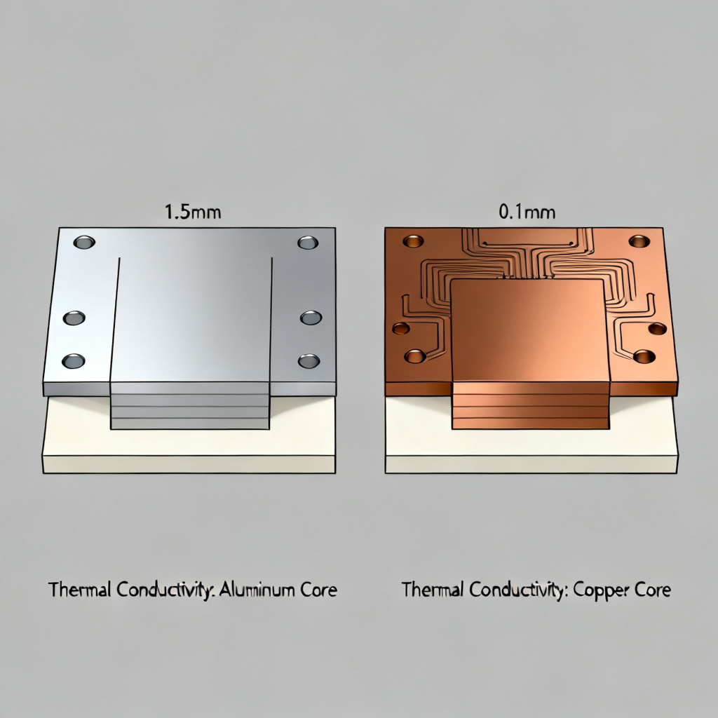
Aluminum core MCPCB is the most common choice due to its balance of cost, thermal performance, and weight. With thermal conductivity of 1–4 W/mK, it is lightweight, corrosion-resistant, and easy to fabricate. Ideal applications include LED streetlights, automotive headlamps, consumer power adapters, and industrial power supplies.
Copper Core MCPCB
Copper core MCPCB provides superior thermal conductivity up to 10+ W/mK for extreme heat applications. However, copper is heavier, more expensive, and harder to machine. Typical uses include high-power laser diodes, RF power amplifiers, military/aerospace electronics, and high-current motor controllers.
| Property | Aluminum Core MCPCB | Copper Core MCPCB |
|---|---|---|
| Thermal Conductivity | 1–4 W/mK | 5–10+ W/mK |
| Cost | Low to moderate | High |
| Weight | Light | Heavy |
| Corrosion Resistance | Good (with coating) | Requires protection |
| Typical Thickness | 0.5–3.0 mm | 0.5–2.0 mm |
MCPCB Layer Structure Explained
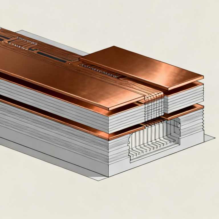
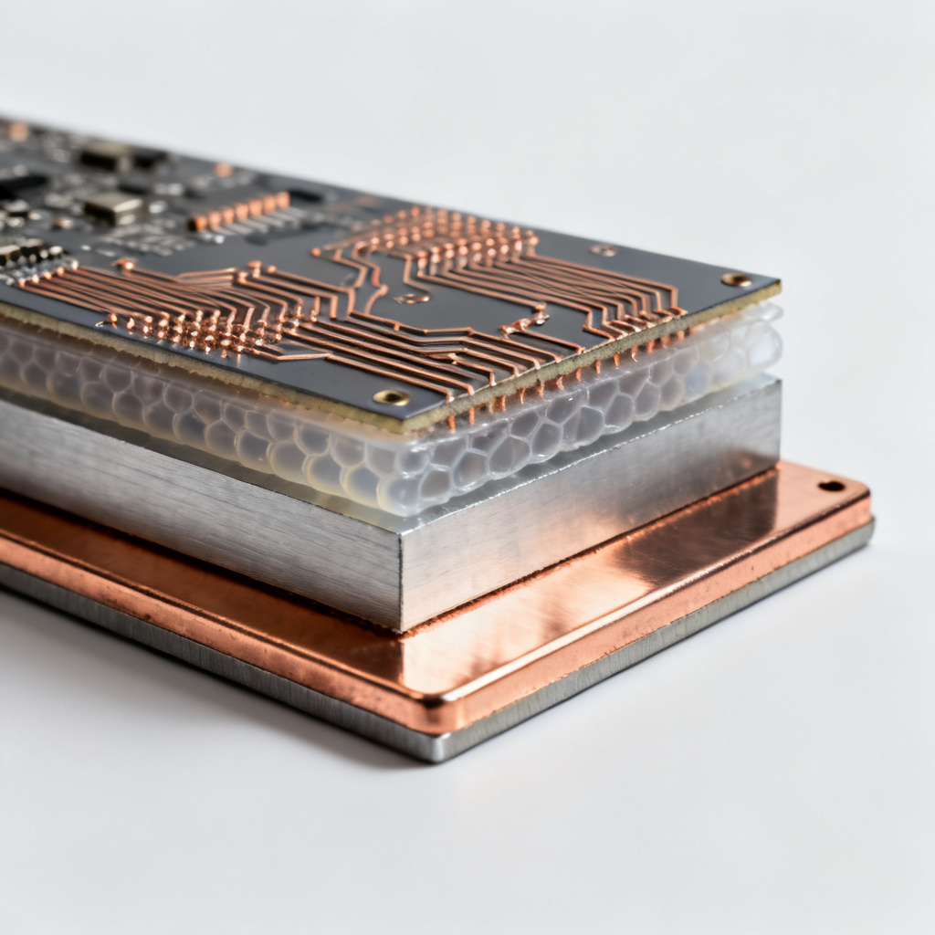
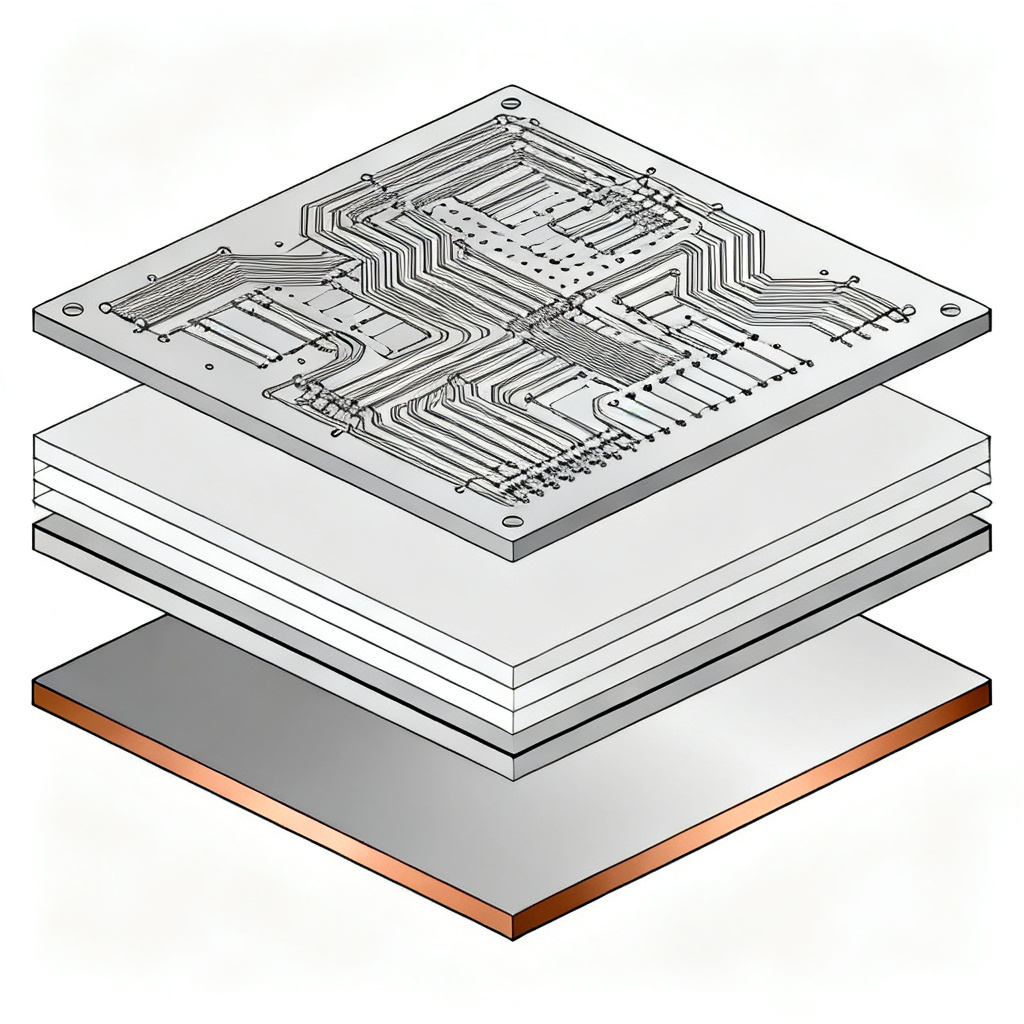
A standard Metal Core PCB consists of three main layers:
- Copper Circuit Layer: Top layer with etched traces, typically 1oz to 4oz copper thickness for high-current paths.
- Dielectric Insulating Layer: Thermally conductive but electrically insulating material (e.g., ceramic-filled epoxy) bonding copper to metal core, thickness 25–150µm.
- Metal Base Layer: Aluminum or copper sheet (0.5–3.0mm) acting as heat sink. May include protective coating like anodizing for aluminum.
Advanced MCPCBs may include additional layers for double-sided or multi-layer designs.
Thermal Management Principles in MCPCB
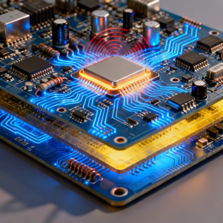
Thermal management in MCPCB relies on conduction and spreading. Heat from components conducts through the copper circuit into the dielectric, then into the metal core which spreads heat laterally. Thermal resistance (Rth) is minimized through proper design. Lower Rth values (5–10°C/W for aluminum, 2–5°C/W for copper) indicate better dissipation. Thermal vias and ground planes enhance heat transfer to the metal core.
Design Considerations for Metal Core PCB
Layer Stackup Planning
Use thicker copper (2oz or 4oz) for high-current paths. Thinner dielectrics (25–50µm) improve thermal transfer but increase capacitance risk. Thicker metal cores (2.0–3.0mm) provide better heat spreading.
Component Placement
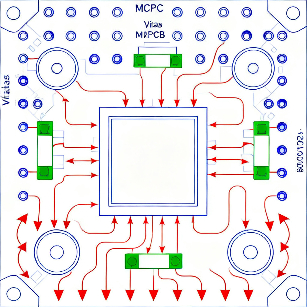
Place heat-generating components near the center of the board. Use thermal pads or copper islands under high-power components. Avoid board edges where heat dissipation is limited.
Routing and Clearance
Keep high-current traces short and wide. Maintain adequate clearance between traces and metal core for high-voltage designs (>100V). Avoid routing sensitive signals near noisy power traces.
Thermal Management Features
Add thermal vias beneath hot components. Use thermally conductive interface material (TIM) between MCPCB and heatsink if needed. Consider edge plating for chassis heat dissipation.
Surface Finish Selection
- HASL: Cost-effective for low-frequency designs.
- ENIG: Flat surface for fine-pitch components and high-frequency circuits.
- OSP: Low cost, environmentally friendly, limited shelf life.
- Hard Gold: For edge connectors or high-wear applications.
MCPCB Manufacturing Process
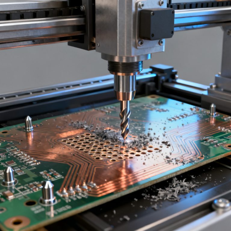
Fabrication of Metal Core PCB involves: metal core preparation (cutting, cleaning, anodizing for aluminum), dielectric lamination under heat and pressure (180–200°C), copper foil lamination, etching, drilling with carbide-tipped bits, plating, surface finish application, and electrical/thermal testing.
Applications of Metal Core PCB
- LED Lighting: Streetlights, automotive headlamps, indoor downlights, UV curing systems.
- Power Electronics: AC-DC converters, motor drives, battery management systems, solar inverters.
- Automotive: Engine control units, brake systems, infotainment displays, EV battery modules.
- Medical: Surgical lighting, diagnostic imaging, patient monitoring.
- Industrial/Military: High-power RF amplifiers, laser diode drivers, radar systems.
MCPCB vs Standard FR4 vs Ceramic PCB
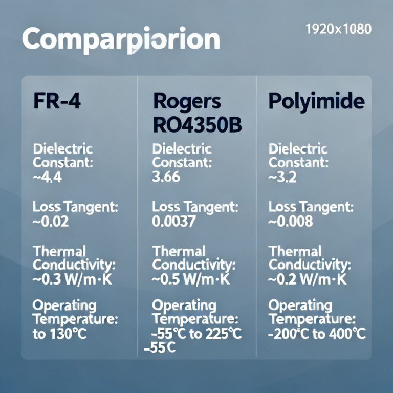
| Property | MCPCB (Aluminum) | Standard FR4 | Ceramic PCB |
|---|---|---|---|
| Thermal Conductivity | 1–4 W/mK | 0.3 W/mK | 20–200 W/mK |
| Cost | Moderate | Low | High |
| Mechanical Strength | High | Moderate | Brittle |
| Weight | Moderate | Light | Heavy |
| Typical Applications | LED, power | Low-power | RF, high-temp |
| Max Operating Temperature | 130–150°C | 130°C | >300°C |
Common Mistakes in MCPCB Design
- Using standard FR4 prepreg instead of thermally conductive dielectric.
- Underestimating copper thickness for high-current paths.
- Placing hot components near board edges.
- Neglecting thermal vias.
- Overlooking corrosion protection for aluminum cores.
- Incorrect thermal simulation instead of using simulation tools.
How to Choose the Right MCPCB
Step 1: Define thermal requirements using Tj = Ta + (P_total × Rth_total). For power dissipation <50W, aluminum MCPCB is sufficient. For 50–200W, consider copper core or thicker aluminum. For >200W, copper core or ceramic PCB may be necessary.
Step 2: Select metal core material based on power levels.
Step 3: Choose dielectric and copper thickness—use 2oz or 4oz for high-current, thicker dielectric for high-voltage.
Step 4: Consider environmental factors—humidity (anodized aluminum or ENIG), vibration (thicker core), temperature extremes (copper core handles up to 200°C).
Step 5: Work with a manufacturer providing detailed specifications and requesting thermal simulation data.
Cost Factors for MCPCB
- Metal Core Material: Aluminum cheaper than copper (2–3x lower cost).
- Core Thickness: Thicker cores increase material cost and drilling time.
- Copper Weight: Higher weight (e.g., 4oz) adds cost.
- Dielectric Type: Advanced dielectrics cost more.
- Surface Finish: ENIG and hard gold more expensive than HASL or OSP.
- Board Size/Complexity: Larger boards and fine-pitch features increase cost.
Typical pricing: aluminum MCPCB $0.05–0.20 per square inch; copper MCPCB $0.15–0.50 per square inch.
Future Trends in Metal Core PCB Technology
Higher thermal conductivity dielectrics (graphene-filled, diamond-based), embedded components, hybrid designs combining MCPCB with FR4 or ceramic, flexible MCPCBs, and sustainable manufacturing through recycling.
Frequently Asked Questions about Metal Core PCB
What is a Metal Core PCB used for?
A Metal Core PCB is used for thermal management in high-power applications such as LED lighting, power electronics, automotive systems, and medical devices. The aluminum or copper base efficiently dissipates heat, improving reliability.
How does aluminum core MCPCB compare to copper core?
Aluminum core MCPCB offers lower cost and lighter weight with thermal conductivity of 1–4 W/mK, while copper core MCPCB provides higher thermal conductivity up to 10+ W/mK but at higher cost and weight. Choose based on thermal requirements and budget.
What is the typical thickness of a Metal Core PCB?
The metal core thickness typically ranges from 0.5mm to 3.0mm for both aluminum and copper base MCPCBs. Thicker cores provide better heat spreading but add weight and cost.
Can MCPCB be used for high-voltage applications?
Yes, but proper dielectric thickness is critical. For voltages above 500V, use a dielectric layer thicker than 100µm to prevent breakdown. Always consult with your MCPCB manufacturer for high-voltage designs.
What surface finish is best for MCPCB?
ENIG is recommended for fine-pitch components and high-frequency circuits. HASL is cost-effective for general use. OSP is environmentally friendly but has limited shelf life. Hard gold is used for edge connectors.
Conclusion: Why Choose Our Metal Core PCB Services
We specialize in custom Metal Core PCB manufacturing with aluminum and copper bases, offering fast turnaround and global shipping. Our team provides free design reviews and thermal simulation to ensure optimal performance. Contact us for a quotation on your next high-power PCB project.