Ultimate Guide to PCB Materials FR4 High Tg Rogers
This Ultimate Guide to PCB Materials FR4 High Tg Rogers covers everything from standard FR4 to advanced Rogers laminates, helping you select the right substrate for performance, reliability, and cost. The wrong material can cause signal loss, thermal failure, or delamination. Whether you design for consumer electronics, aerospace, or 5G, understanding these materials ensures your product meets electrical, thermal, and mechanical requirements.
Core Concepts of PCB Materials
Dielectric Constant (Dk) and Dissipation Factor (Df)
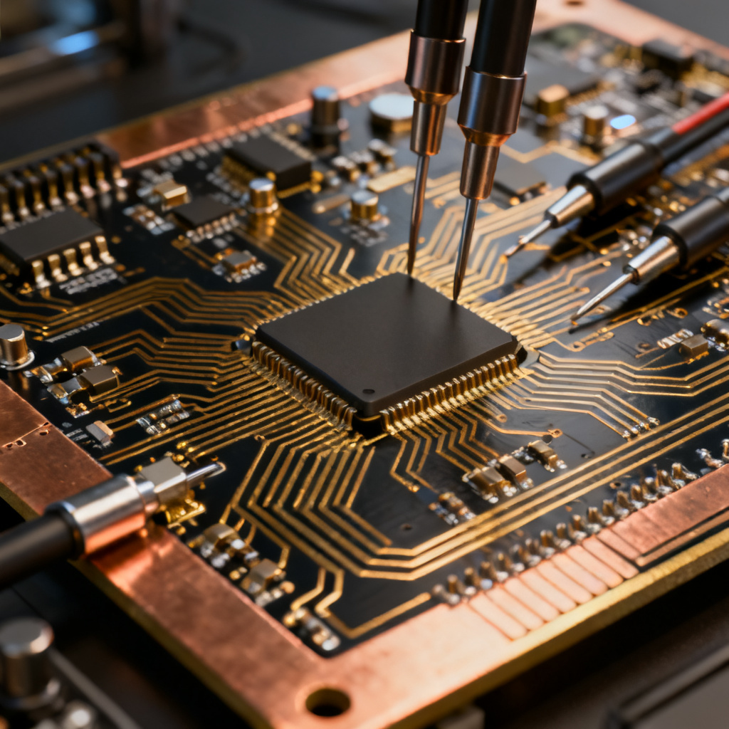
Every PCB material consists of a dielectric insulator laminated with copper foil. Key parameters include Dielectric Constant (Dk), Dissipation Factor (Df), Glass Transition Temperature (Tg), and Coefficient of Thermal Expansion (CTE). Dk measures how much the material slows electromagnetic waves; stable low Dk (3.0–4.5) is critical for high-speed signals. Df indicates signal loss as heat; lower Df (<0.005) is better for RF and microwave applications.
Glass Transition Temperature (Tg) and CTE
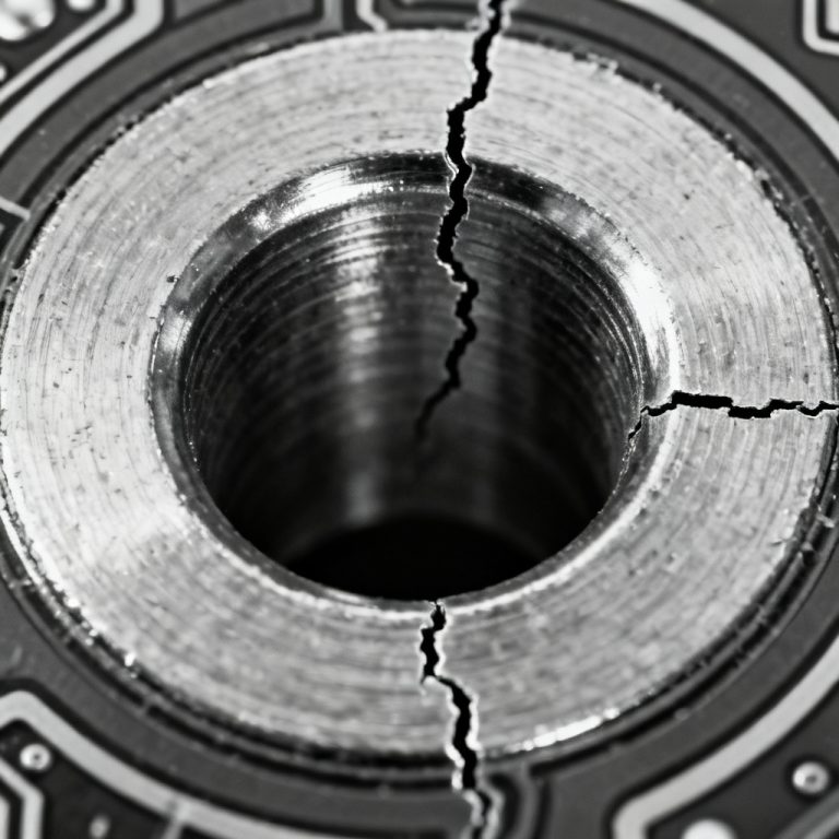
Tg is the temperature where resin changes from rigid to rubbery. Higher Tg (>170°C) ensures dimensional stability during soldering. CTE describes expansion with heat; low Z-axis CTE prevents via barrel cracking. Thermal conductivity (k) above 1.0 W/mK is essential for power electronics.
FR4: The Industry Standard PCB Material
What Is FR4?
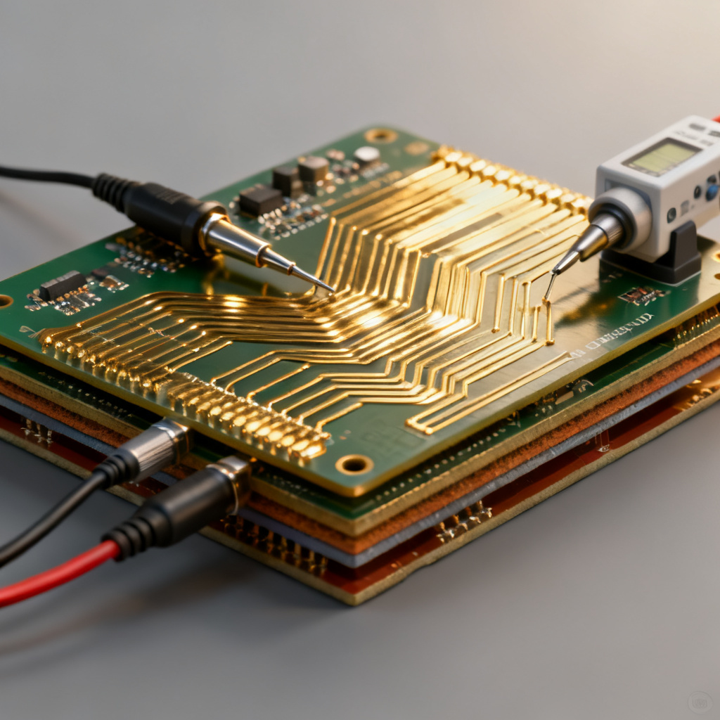
FR4 is glass-reinforced epoxy laminate, the most widely used PCB material. “FR” stands for Flame Retardant (UL94 V-0). Grades include standard (Tg 130–140°C), mid-Tg (150–160°C), and high-Tg (170–180°C). Typical properties: Dk 4.2–4.5, Df 0.02, CTE 50–70 ppm/°C, thermal conductivity 0.3 W/mK.
Advantages and Limitations of FR4
FR4 is cost-effective, mechanically strong, and easy to process. However, high Df (0.02) limits use above 1 GHz. Poor thermal conductivity and high CTE reduce reliability in high-power or high-temperature environments. Moisture absorption can degrade electrical properties.
Common Applications of FR4
Consumer electronics, low-power industrial controls, automotive infotainment, LED lighting, and prototyping.
High‑Tg Materials for Thermal Stability
What Is High‑Tg?
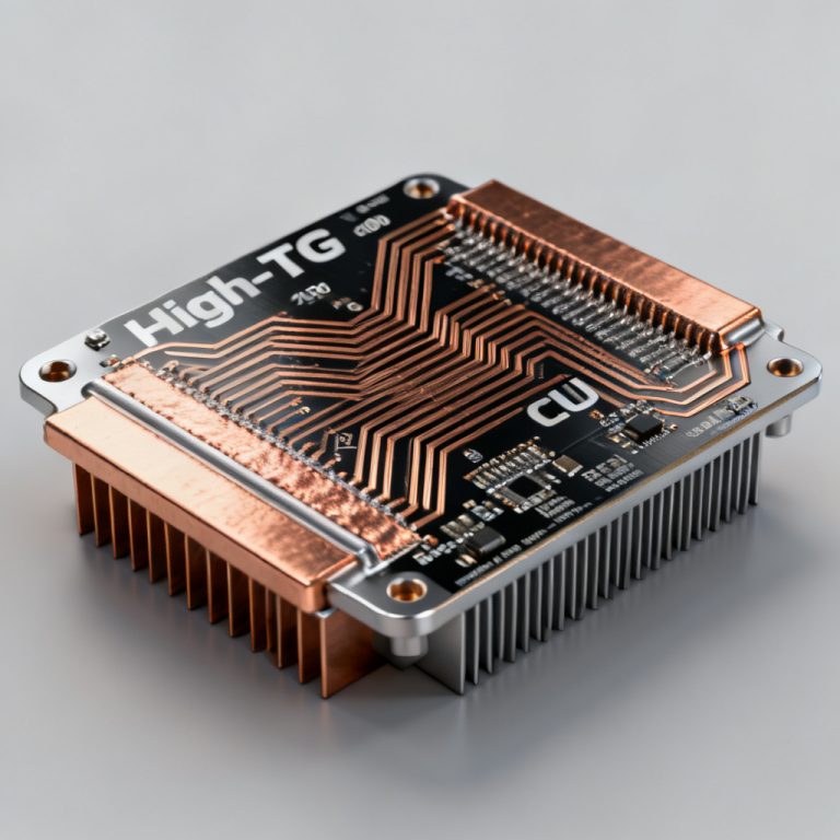
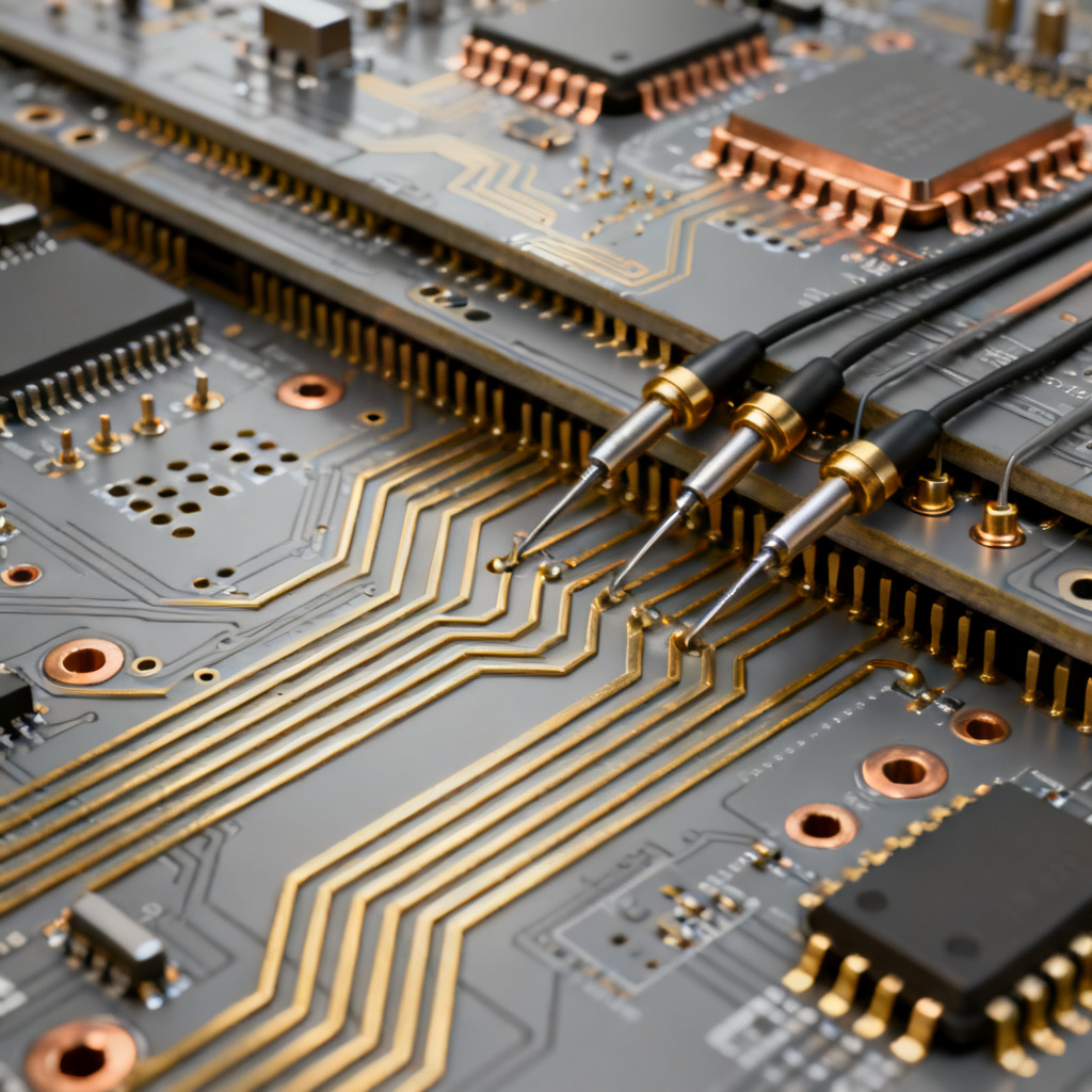
High‑Tg PCB materials (e.g., Isola 370HR, Shengyi S1000-2M) have Tg above 170°C, typically 170–180°C. Some reach 200°C+ (polyimide). Key differences from standard FR4: lower CTE (40–50 ppm/°C), better thermal resistance for lead-free reflow (260°C peak), and 10–20% higher cost.
When to Choose High‑Tg
Multi-layer boards (8+ layers), lead-free soldering, automotive under-hood electronics, high-power LED drivers, and industrial/military applications requiring extended thermal cycling.
High‑Tg Variants
Mid-Tg (150–160°C), High-Tg (170–180°C), and Ultra-High-Tg (200°C+, polyimide or BT-epoxy). Note: High-Tg does not guarantee high thermal conductivity; for heat dissipation, use metal-core PCBs or thermal laminates.
High‑Frequency Materials: Rogers, Teflon, and More
Why Specialized RF Materials?
Above 1 GHz (5G, Wi‑Fi 6E, radar), standard FR4’s high Df and unstable Dk cause unacceptable loss. High-frequency laminates offer low loss, stable Dk, and tight tolerances.
Rogers Laminates
Rogers RO4000 Series (RO4350B, RO4003C)
Dk 3.48 (RO4350B), Df 0.0037 at 10 GHz, Tg >280°C. Combines high-frequency performance with FR4-like processing. Applications: 5G base stations, automotive radar (77 GHz), IoT modules.
Rogers RT/duroid Series (5880, 6002, 6010)
Dk 2.20 (5880) to 10.2 (6010), Df as low as 0.0009 at 10 GHz. PTFE-based, extremely low loss for mmWave (up to 100 GHz). Requires careful handling; often used in hybrid stacks.
Rogers RO3000 Series (RO3003, RO3010)
Dk 3.0 (RO3003) to 10.2 (RO3010), Df 0.0013 at 10 GHz. Ceramic-filled PTFE for improved dimensional stability. Applications: automotive radar, wireless infrastructure.
Other High‑Frequency Materials
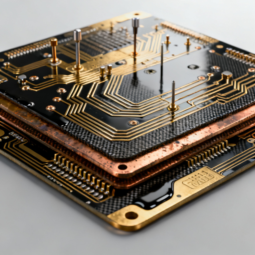
PTFE (Teflon) laminates (Taconic, Arlon) – lowest Df (0.0005–0.002), low moisture absorption, but difficult to machine. Polyimide (Kapton) – Tg 250–300°C, good for flex and high-temp. Hydrocarbon/ceramic laminates (Isola Astra MT) – low loss, stable Dk, often lower cost than Rogers.
Hybrid Stackup Design
Combine outer layers of high-frequency material (e.g., Rogers RO4350B) with inner FR4 layers to balance cost and performance. Use compatible bondply (e.g., Rogers 4450F). Consider CTE mismatch, optimized drilling, and plasma treatment for PTFE.
Specialized PCB Materials
Metal‑Core PCBs (MCPCBs)
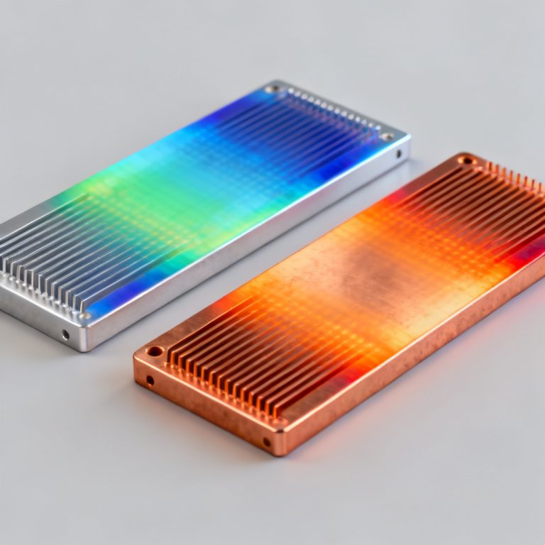
Dielectric layer bonded to aluminum or copper base. Thermal conductivity 1.0–10.0 W/mK. Applications: high-power LEDs, power converters, automotive headlights.
Flex and Rigid‑Flex Materials
Flexible substrates: polyimide (Kapton), PET. Rigid-flex combines FR4 with polyimide layers. Key properties: high flexibility, thin profile (0.05–0.2mm). Applications: wearables, medical devices, foldable electronics.
Ceramic‑Filled PTFE Composites
Low CTE matching copper, low Df, thermal conductivity 0.5–1.0 W/mK. Applications: power RF amplifiers, antenna arrays.
BT‑Epoxy and Low‑CTE Materials
BT-epoxy: Tg 180–200°C, low CTE, used for IC substrates and HDI boards. Low-CTE materials (e.g., TMM) match ceramic packages to reduce solder joint stress.
How to Select the Right PCB Material
Step 1: Define Electrical Requirements
Frequency below 1 GHz → FR4. 1–10 GHz → Rogers RO4000 or hydrocarbon. Above 10 GHz → RT/duroid or PTFE. For high-speed digital (PCIe Gen 5, 100G Ethernet), choose Df < 0.005 and stable Dk.
Step 2: Assess Thermal Environment
Operating temperature below 130°C → standard FR4. 130–170°C → high-Tg FR4. Above 170°C → polyimide or BT-epoxy. For high power dissipation, consider MCPCB or thermal laminates.
Step 3: Evaluate Mechanical and Manufacturing Constraints
Thick boards (3.2mm) may require high-Tg to prevent warpage. Need flex → polyimide. 8+ layers → high-Tg recommended. Rogers RO4000 processes like FR4; PTFE requires plasma etching and slow drilling. Cost order: standard FR4 < high-Tg FR4 < Rogers RO4000 < RT/duroid < PTFE.
Step 4: Check Reliability Standards
UL94 V-0, IPC-4101 (FR4 is /21, high-Tg is /24 or /99), AEC-Q200 for automotive. Use CAF-resistant resins for high humidity environments.
Common Material Pitfalls
CAF Growth
Under high humidity and voltage, copper ions migrate along glass fibers. Solution: CAF-resistant FR4 or high-Tg materials with tighter glass weave.
Delamination During Soldering
Bake boards at 125°C for 4–8 hours before soldering. Use high-Tg materials for lead-free processes.
Impedance Variation
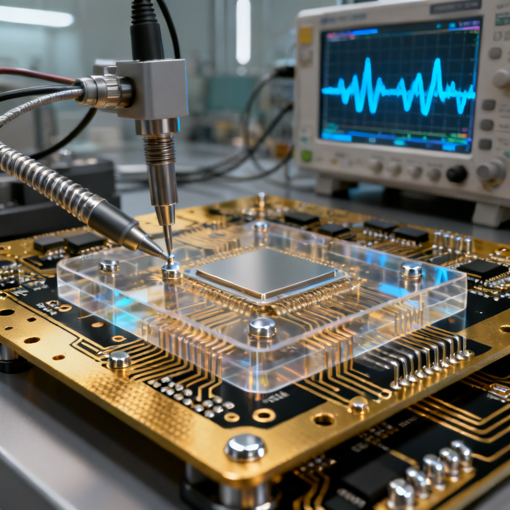
FR4 Dk tolerance ±0.25 causes mismatch. Specify tight Dk tolerance materials (Rogers ±0.05) and use controlled impedance testing.
Copper Foil Roughness
Rough copper increases conductor loss at high frequencies. Use reverse-treated or ultra-smooth copper (RTF, VLP) for RF layers.
PCB Materials Comparison Table
| PCB Material Type | Dk (1 GHz) | Df (1 GHz) | Tg (°C) | CTE Z (ppm/°C) | Thermal Cond. (W/mK) | Relative Cost | Typical Applications |
|---|---|---|---|---|---|---|---|
| Standard FR4 | 4.2–4.5 | 0.02 | 130–140 | 50–70 | 0.3 | Low | General purpose |
| High-Tg FR4 | 4.2–4.5 | 0.02 | 170–180 | 40–50 | 0.3 | Medium | Multi-layer, lead-free, automotive |
| Rogers RO4350B | 3.48 | 0.0037 | >280 | 30–40 | 0.6 | High | 5G, radar, RF |
| Rogers RT/duroid 5880 | 2.20 | 0.0009 | >260 (PTFE) | 30–40 | 0.2 | Very High | mmWave, satellite |
| Polyimide (Kapton) | 3.5 | 0.002–0.005 | 250–300 | 30–50 | 0.2 | High | Flex, high-temp |
| Aluminum MCPCB | N/A | N/A | N/A | N/A | 1.0–10.0 | Medium | LED, power |
| BT-Epoxy | 3.8–4.2 | 0.005–0.01 | 180–200 | 30–40 | 0.3 | Medium | IC substrates |
FAQ: PCB Materials Guide
What is the best PCB material for high-frequency applications?
For frequencies above 1 GHz, Rogers laminates (RO4000, RT/duroid) or PTFE-based materials offer low Df and stable Dk. This PCB materials guide recommends RO4350B for 5G and RT/duroid 5880 for mmWave.
How does high-Tg FR4 differ from standard FR4?
High-Tg FR4 has Tg above 170°C, lower CTE, and better resistance to lead-free soldering. It is ideal for multi-layer boards and automotive electronics, as detailed in this PCB materials guide.
Can I mix FR4 with Rogers materials in one board?
Yes, hybrid stackups combine Rogers outer layers with FR4 inner layers to balance cost and performance. Use compatible bondply and consider CTE mismatch.
What is the most cost-effective PCB material?
Standard FR4 is the most economical for general-purpose designs. For higher thermal or frequency requirements, high-Tg FR4 or Rogers RO4000 series provide good value.
How do I prevent CAF growth in PCB materials?
Use CAF-resistant FR4 or high-Tg materials with tighter glass weave. Proper board baking and conformal coating also help.
Future Trends in PCB Materials
Low-loss materials for 112G/224G SerDes (Df < 0.001), thermally conductive dielectrics with k > 10 W/mK for EV power modules, sustainable halogen-free resins, and 3D-printed PCBs with graded Dk are emerging.
Conclusion
Selecting the right PCB material is critical for performance, reliability, and cost. Standard FR4 suits most general applications; high-Tg provides thermal stability; Rogers and PTFE laminates deliver low loss for RF and high-speed designs. At [Your Company Name], we manufacture PCBs using a wide range of materials—from FR4 to advanced Rogers. Contact us for a free material consultation and quote.