High Frequency Materials Rogers PTFE Isola Taconic
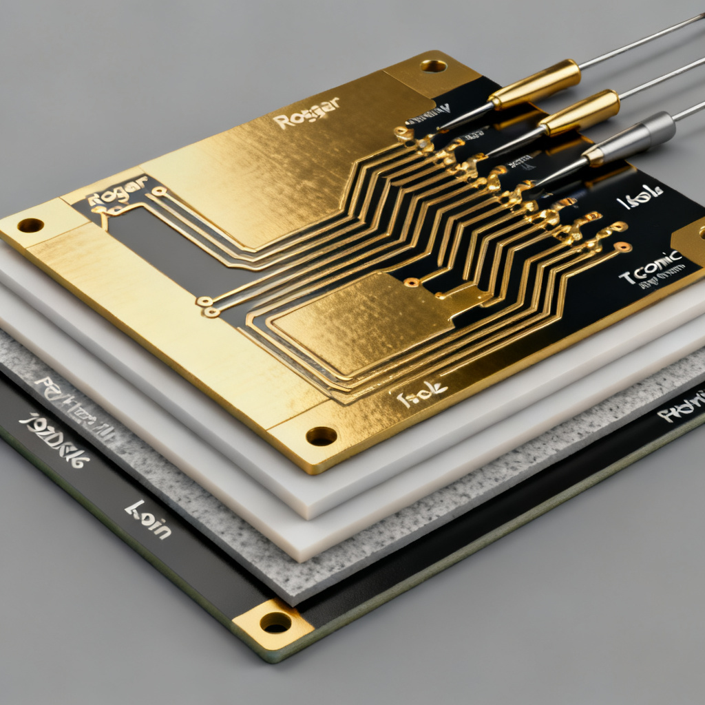
In high‑frequency PCB design, selecting the right High Frequency Materials Rogers PTFE Isola Taconic is critical for signal integrity and low loss. Standard FR‑4 fails above a few hundred MHz, making specialized laminates mandatory for 5G, radar, and aerospace. This guide covers all key parameters, product families, and selection criteria.
Why Standard FR‑4 Fails at High Frequencies
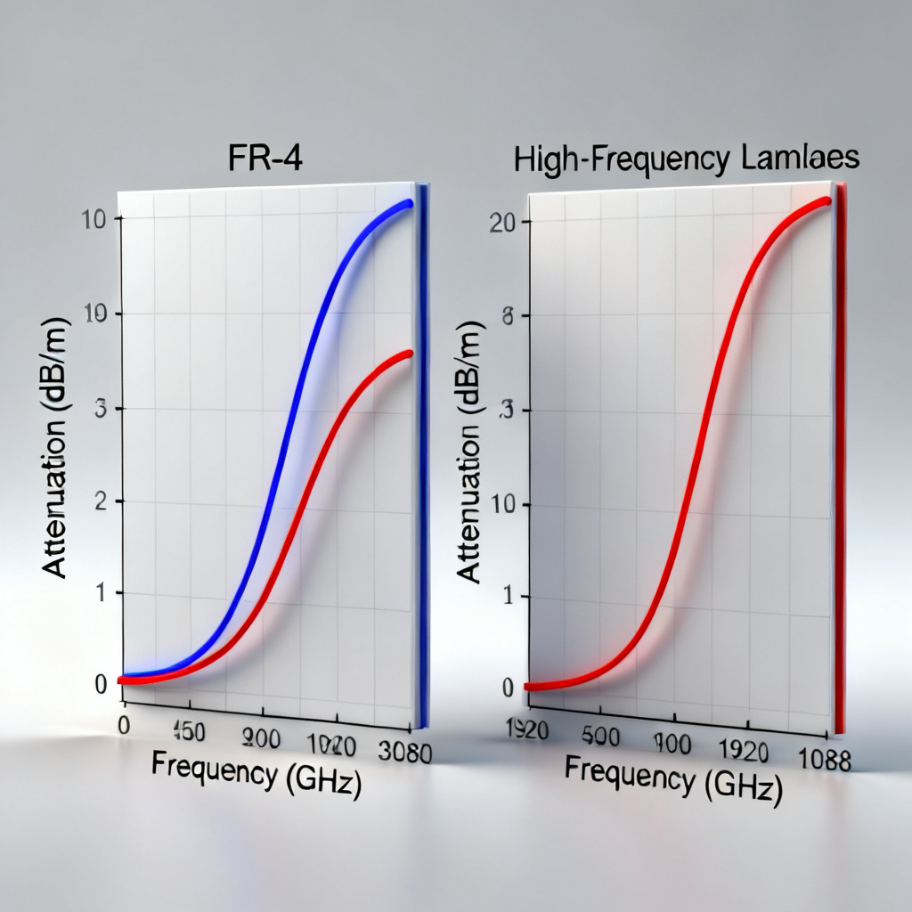
Before exploring High‑Frequency Materials, understand why FR‑4 is inadequate. Its dielectric constant (Dk) varies from 4.2 to 4.8 with ±10% tolerance, and dissipation factor (Df) is 0.02 at 1 GHz, causing excessive signal loss. Poor thermal stability and high moisture absorption degrade RF circuits above 1 GHz, leading to impedance mismatches and unreliable operation. Hence, specialized laminates like Rogers, PTFE, Isola, and Taconic are mandatory.
Core Electrical Parameters for High‑Frequency Materials
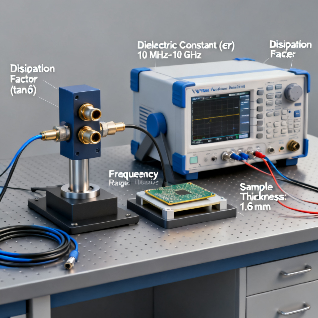
To compare High‑Frequency Materials, focus on these parameters:
- Dielectric Constant (Dk or εr): Determines signal propagation speed and impedance. Low Dk (2.2–3.5) is typical.
- Dissipation Factor (Df or tan δ): Measures energy loss. Low Df (0.0009–0.005) minimizes attenuation.
- Thermal Coefficient of Dk (TCDk): Low TCDk (< 50 ppm/°C) ensures stable performance.
- Thermal Conductivity: Important for heat dissipation in high‑power RF circuits.
- Coefficient of Thermal Expansion (CTE): Low CTE improves plated‑through‑hole (PTH) reliability.
- Moisture Absorption: Low absorption (< 0.1%) prevents Dk shift.
- Glass Transition Temperature (Tg): High Tg (> 200°C) ensures mechanical stability.
Rogers High‑Frequency Laminates
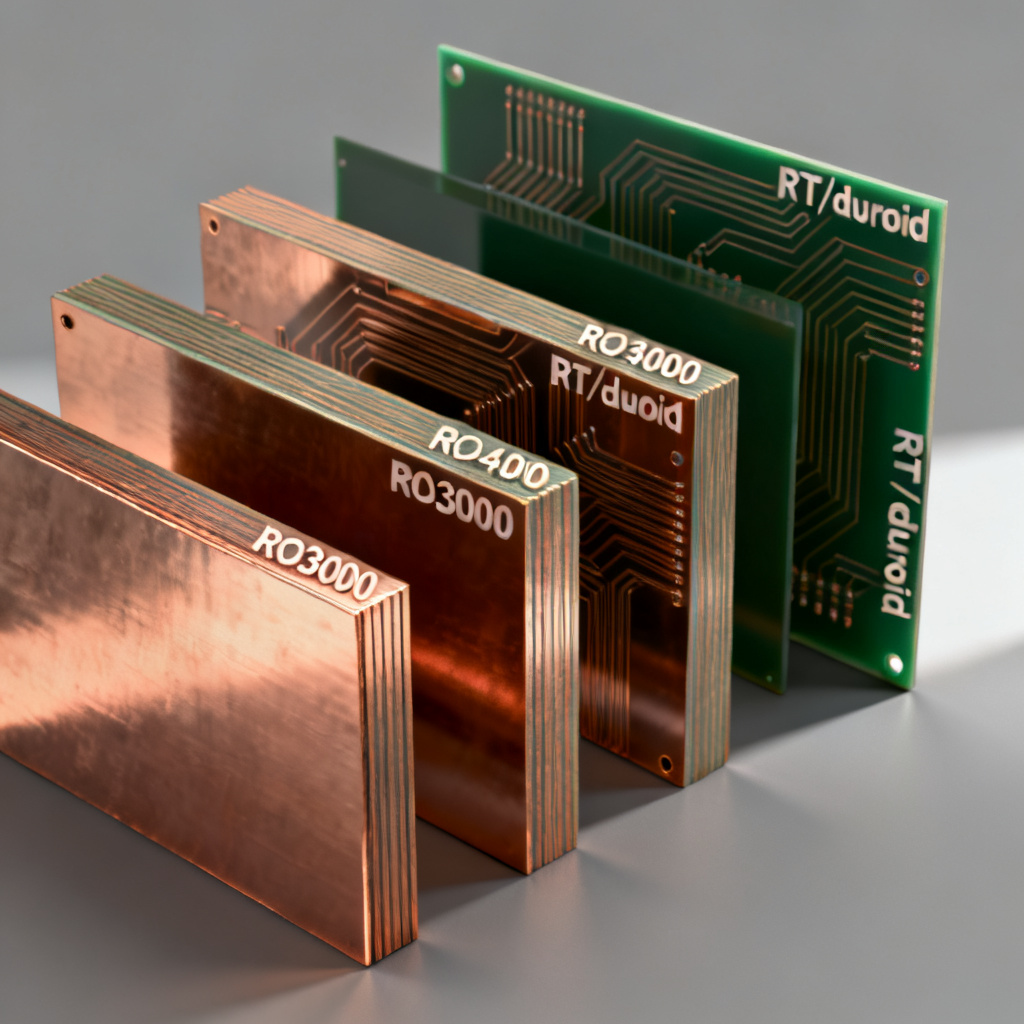
Rogers Corporation leads the industry with a wide range of High‑Frequency Materials optimized for various performance and cost requirements.
Rogers RO3000® Series (Ceramic‑filled PTFE Composites)
Key laminates: RO3003™, RO3006™, RO3010™. Dk range: 3.0 (RO3003) to 10.2 (RO3010). Features include excellent Dk tolerance (±0.05 for RO3003), low Df (0.0010–0.0020 at 10 GHz), and very low TCDk (< 50 ppm/°C). RO3003 is ideal for millimeter‑wave circuits up to 100 GHz. Applications: automotive radar, 5G antennas, satellite communications.
Rogers RO4000® Series (Hydrocarbon/Ceramic, Non‑PTFE)
Key laminates: RO4003C™, RO4350B™. Dk: 3.38 (RO4003C) to 3.48 (RO4350B). Df: 0.0027 (RO4003C) and 0.0037 (RO4350B) at 10 GHz. Compatible with standard FR‑4 processing, no plasma needed. RO4350B has higher thermal conductivity (0.62 W/m/K). Applications: wireless infrastructure, power amplifiers, base stations.
Rogers RT/duroid® (PTFE/Glass and PTFE/Ceramic)
Key laminates: RT/duroid 5870, 5880, 6002, 6010LM. Dk: 2.2 (5880) to 10.2 (6010LM). Extremely low Df: 0.0009 (5880) and 0.0012 (5870) at 10 GHz. RT/duroid 5880 is the gold standard for low‑loss applications. RT/duroid 6002 has TCDk < 10 ppm/°C. Applications: military radar, satellite antennas, test equipment.
Rogers TMM® (Thermoset Microwave Materials)
Key laminates: TMM 3, TMM 4, TMM 6, TMM 10. Dk: 3.27 (TMM 3) to 9.2 (TMM 10). Low Df (0.0020–0.0022 at 10 GHz). High thermal conductivity (up to 0.84 W/m/K). Compatible with standard PCB processes. Applications: power amplifiers, high‑reliability RF circuits.
PTFE (Teflon) Laminates
PTFE‑based High‑Frequency Materials are prized for ultra‑low loss and low Dk, used in the most demanding applications.
Pure PTFE (e.g., Rogers RT/duroid 5880, Taconic TLY‑5)
Dk: 2.2. Df: 0.0009 (among the lowest). Extremely low moisture absorption (< 0.02%). Challenges: soft material, poor thermal conductivity (0.2 W/m/K), requires plasma etching. Applications: millimeter‑wave antennas, space‑based radar.
Ceramic‑Filled PTFE (e.g., Rogers RO3000, Taconic RF‑35)
Dk: 2.94 (RF‑35) to 10.2 (RO3010). Df: 0.0015–0.0025. Lower CTE than pure PTFE, better PTH reliability. Applications: wideband antennas, filters.
Woven Glass Reinforced PTFE (e.g., Rogers RT/duroid 5870, Taconic TLC‑32)
Dk: 2.33 (TLC‑32) to 2.94 (RT/duroid 5870). Improved dimensional stability. Df: 0.0012–0.0020. Applications: multilayer RF boards.
Isola High‑Frequency Laminates
Isola offers cost‑effective High‑Frequency Materials with good electrical performance.
Isola IS620 and IS680 (Modified Epoxy, Non‑PTFE)
Dk: 3.4–3.6 (IS620) and 3.0–3.2 (IS680). Df: 0.005 (IS620) to 0.002 (IS680) at 1 GHz. Tg > 200°C. Compatible with standard FR‑4 processing. Applications: high‑speed digital, wireless backhaul.
Isola I‑Tera® MT40 (Low‑Loss, Non‑PTFE)
Dk: 3.45. Df: 0.003 at 10 GHz. Low moisture absorption (0.1%). Thermal conductivity 0.5 W/m/K. Excellent for multilayer stackups with FR‑4 hybrid designs. Applications: 5G antennas, small cells.
Isola Astra® MT77 (Very Low Loss)
Dk: 3.0. Df: 0.0017 at 10 GHz. One of the lowest loss non‑PTFE materials. Low CTE and high Tg (280°C). Applications: 77 GHz radar, satellite communications.
Isola FR‑408 (High‑Speed FR‑4)
Dk: 3.8–4.0. Df: 0.012 at 1 GHz. Improved over standard FR‑4 for high‑speed digital. Not suitable for RF above 3 GHz. Applications: high‑speed digital boards.
Taconic High‑Frequency Laminates
Taconic specializes in PTFE‑based High‑Frequency Materials known for low loss and excellent thermal properties.
Taconic TLY Series (PTFE/Woven Glass)
Key laminates: TLY‑5, TLY‑5A, TLY‑3. Dk: 2.2 (TLY‑5) to 2.33 (TLY‑3). Df: 0.0009 (TLY‑5) to 0.0013 (TLY‑3). Excellent Dk tolerance (±0.02). Applications: millimeter‑wave, space, military.
Taconic RF Series (Ceramic‑Filled PTFE)
Key laminates: RF‑35, RF‑60, RF‑10. Dk: 3.5 (RF‑35) to 10.0 (RF‑10). Df: 0.0018–0.0025. Good thermal conductivity (0.6 W/m/K for RF‑35). Applications: base station antennas, couplers.
Taconic TLX Series (Low Loss, Non‑PTFE)
Key laminates: TLX‑8, TLX‑9. Dk: 2.55 (TLX‑8) to 2.95 (TLX‑9). Df: 0.0012 (TLX‑8) to 0.0020 (TLX‑9). Compatible with standard processes. Applications: high‑speed digital, automotive radar.
Taconic FastRise® (High Tg, Low Loss)
Dk: 3.0–3.5. Designed for high‑reliability, high‑temperature applications. Applications: aerospace, automotive.
Comparison Table: High‑Frequency Materials
| Parameter | Rogers RO4003C | Rogers RT/duroid 5880 | Isola Astra MT77 | Taconic TLY‑5 | Taconic RF‑35 |
|---|---|---|---|---|---|
| Dk (10 GHz) | 3.38 | 2.20 | 3.00 | 2.20 | 3.50 |
| Df (10 GHz) | 0.0027 | 0.0009 | 0.0017 | 0.0009 | 0.0018 |
| TCDk (ppm/°C) | +40 | -125 | +50 | -125 | +30 |
| Thermal Cond. (W/m/K) | 0.64 | 0.20 | 0.50 | 0.20 | 0.60 |
| CTE (Z‑axis, ppm/°C) | 45 | 240 | 50 | 240 | 70 |
| Moisture Absorption (%) | 0.06 | 0.02 | 0.10 | 0.02 | 0.05 |
| Process Compatibility | Standard FR‑4 | Plasma required | Standard FR‑4 | Plasma required | Standard FR‑4 |
| Cost | Medium | High | Medium | High | Medium |
Key takeaways: Lowest loss: Rogers RT/duroid 5880 and Taconic TLY‑5 (Df = 0.0009). Best temperature stability: Rogers RO4003C and Isola Astra MT77. Easiest manufacturing: Rogers RO4000 series and Isola I‑Tera. Highest thermal conductivity: Taconic RF‑35 and Rogers TMM series.
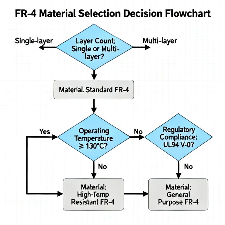
Selecting the Right Material for Your Application
Choosing High‑Frequency Materials depends on application requirements:
For Millimeter‑Wave (30 GHz and above)
Recommended: Rogers RO3003, RT/duroid 5880, Taconic TLY‑5. Ultra‑low Df and stable Dk are non‑negotiable.
For 5G Base Stations and Antennas
Recommended: Rogers RO4350B, Isola I‑Tera MT40, Taconic RF‑35. Good balance of low loss, thermal performance, and manufacturability.
For Automotive Radar (77 GHz)
Recommended: Rogers RO3003, Isola Astra MT77. Very low loss, low TCDk, and high reliability under thermal cycling.
For High‑Power RF Amplifiers
Recommended: Rogers TMM series, Taconic RF‑35. Higher thermal conductivity for efficient heat dissipation.
For Cost‑Sensitive High‑Frequency Designs
Recommended: Isola IS680, Rogers RO4003C. Low cost, compatible with standard FR‑4 processes.
For Military and Space Applications
Recommended: Rogers RT/duroid 5880, Taconic TLY‑5, Rogers RO3003. Highest reliability and low outgassing.
Manufacturing and Design Considerations
Working with High‑Frequency Materials requires specialized processes:
Handling PTFE‑Based Materials
Plasma treatment required for hole wall activation. Drilling: use carbide drills with high spindle speed (80k–100k RPM). PTFE is soft; avoid scratches. Layer registration: compensate for high CTE during lamination.
Multilayer Stackups with Hybrid Materials
Common practice: use low‑loss core (e.g., RO4350B) with standard FR‑4 prepreg. Use bondplies like Rogers 4450F or Taconic 35P. Account for Dk variations in prepreg materials.
Thermal Management
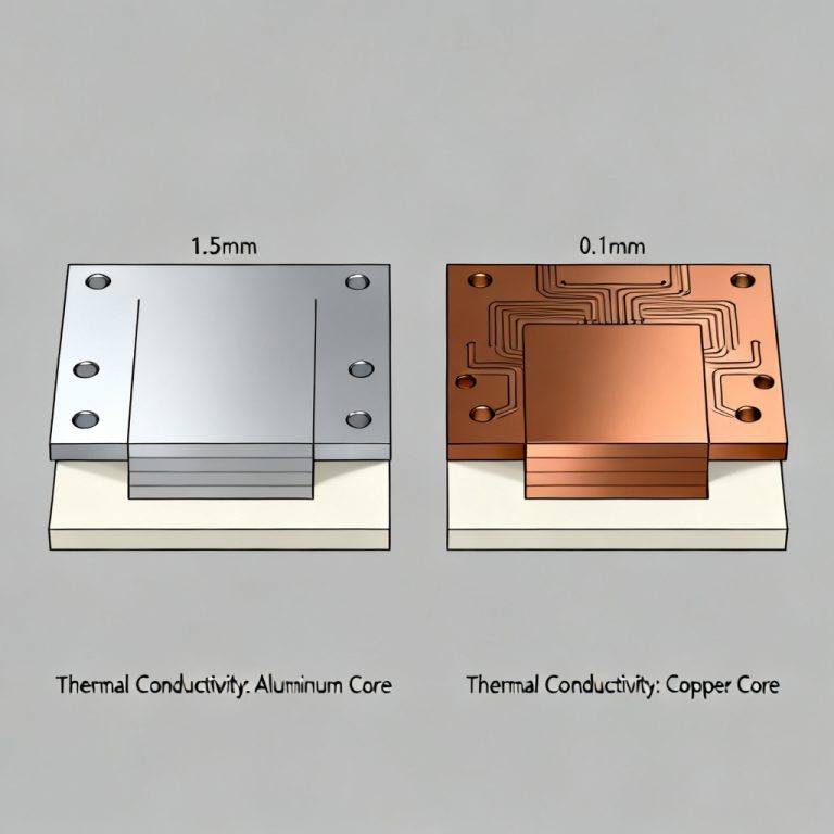
High‑power RF circuits often require metal‑backed PCBs (e.g., Rogers 6035HTC with aluminum base). Use thermal vias under power devices.
Testing and Verification
Use TDR for impedance testing. Measure Dk and Df with a resonant cavity or SPDR at target frequency. Perform thermal cycling tests for PTH reliability.
Future Trends in High‑Frequency Materials
Low‑loss, low‑cost alternatives like Isola Astra MT77 and Rogers RO4000 series continue to improve. Higher thermal conductivity through new ceramic fillers. Hybrid laminates combining PTFE and thermoset resins. Demand for Df < 0.001 at 100 GHz drives innovation in LCP and advanced PTFE formulations.