High Tg PCB Guide Advantages Materials Applications
This High Tg PCB Guide Advantages Materials Applications explains everything you need to know about glass transition temperature, material selection, and thermal reliability. High‑Tg PCBs are essential for automotive, aerospace, and industrial electronics that demand stable performance under extreme heat.
Whether you are designing a power inverter, an engine control unit, or a satellite communication module, understanding High‑Tg PCB properties ensures your product meets the highest reliability standards. This pillar page covers advantages, materials, applications, design tips, and frequently asked questions.
1. What Is a High‑Tg PCB?
A High‑Tg PCB is a printed circuit board manufactured using a laminate material with a glass transition temperature (Tg) significantly higher than standard FR‑4. Tg is the temperature at which the polymer matrix in the laminate transitions from a rigid, glassy state to a soft, rubbery state. For standard FR‑4, Tg is typically around 130–140°C. High‑Tg laminates, by contrast, have a Tg of 170°C or higher—commonly 170°C, 180°C, or even 200°C+.
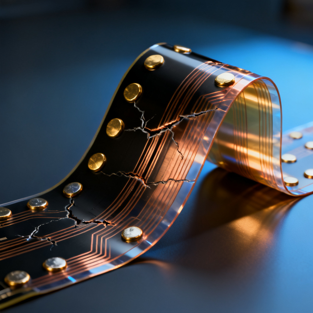
When the High‑Tg PCB exceeds its Tg, the material begins to soften, expand, and lose mechanical strength, leading to issues like delamination, warpage, and via cracking. High‑Tg materials are engineered to maintain dimensional stability, electrical insulation, and mechanical integrity at elevated temperatures, making them essential for applications requiring thermal reliability.
2. Why Is High‑Tg Important? (Key Advantages)
2.1 Superior Thermal Stability
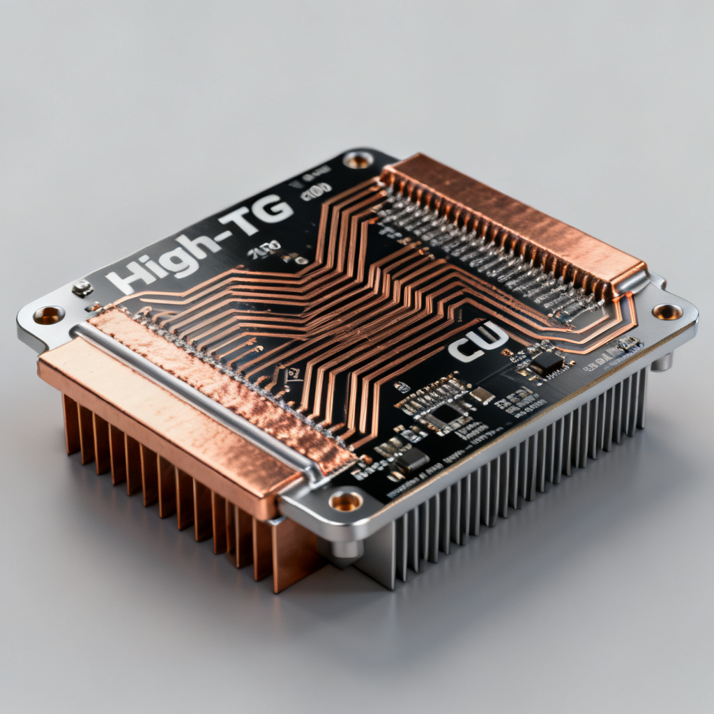
High‑Tg PCB materials withstand prolonged exposure to high operating temperatures without degrading. They resist thermal expansion (low CTE – Coefficient of Thermal Expansion), reducing stress on copper traces, plated through‑holes, and solder joints. This is critical in power electronics, automotive under‑hood electronics, and industrial controls.
2.2 Enhanced Mechanical & Dimensional Stability
At high temperatures, standard FR‑4 expands and softens, causing misalignment of multilayer layers and potential circuit failures. High‑Tg PCB materials maintain rigidity, preventing warp and twist during reflow soldering and actual operation. This stability also improves yield during assembly.
2.3 Resistance to Delamination & Cracking
High‑Tg PCB laminates have stronger bond strength between resin and glass fiber, resisting delamination even after multiple thermal cycles. This is vital for lead‑free soldering processes (higher reflow temperatures) and for PCBs that experience thermal shock.
2.4 Improved Electrical Performance at High Temperatures
Dielectric constant (Dk) and dissipation factor (Df) remain more stable over a wider temperature range, ensuring consistent signal integrity in high‑frequency or high‑power circuits.
2.5 Longer Product Lifespan in Harsh Environments
By preventing material degradation, High‑Tg PCB materials extend the operational life of electronic assemblies in high‑temperature, high‑humidity, or chemically aggressive environments.
3. Common High‑Tg Materials & Their Properties
3.1 High‑Tg FR‑4 (e.g., IT‑180, S1000‑2, EM‑827)
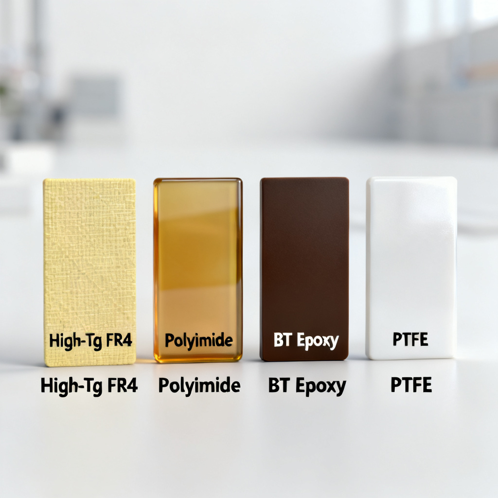
High‑Tg PCB grade FR‑4 has a Tg of 170–180°C. It uses modified epoxy resin with higher crosslink density, offering a good balance of cost and thermal performance. It is compatible with standard PCB fabrication processes and is widely used in multilayer boards for automotive, telecom, and industrial electronics.
3.2 Polyimide (e.g., DuPont Kapton, Pyralux)
Polyimide laminates have a Tg of 250–300°C or higher, with exceptional thermal and chemical resistance. They are available in flexible or rigid forms but require higher cure temperatures and more demanding processing. Applications include aerospace, military, downhole drilling, and high‑reliability flex circuits.
3.3 BT Epoxy (Bismaleimide Triazine)
BT epoxy offers a Tg of 180–220°C with low dielectric loss, low CTE, and excellent thermal stability. It is often used in IC substrates and high‑speed digital boards, including chip packaging, high‑density interconnect (HDI), and server motherboards.
3.4 PTFE (Teflon) Composites (with ceramic fillers)
PTFE composites have a Tg typically above 260°C (PTFE itself has no sharp Tg; composite Tg depends on filler). They provide ultra‑low Dk/Df and excellent high‑frequency performance, but are difficult to bond and process. Applications include RF/microwave, 5G, and satellite communications.
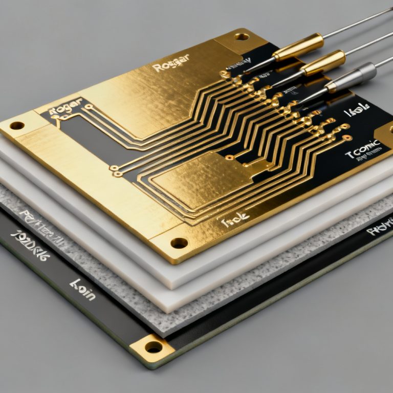
3.5 Ceramic‑Filled Laminates (e.g., Rogers 4350B, Arlon 85N)
These materials have a Tg of 200–280°C depending on formulation, with low CTE, high thermal conductivity, and stable electrical properties over temperature. They are used in power amplifiers, RF modules, and automotive radar.
3.6 Epoxy‑Based High‑Tg with Halogen‑Free Options
Halogen‑free High‑Tg PCB materials meet RoHS and REACH requirements, with a Tg of 170–180°C. They have lower thermal conductivity than ceramic‑filled types but are adequate for most industrial needs, such as consumer electronics requiring lead‑free soldering and LED lighting.
4. How to Select the Right High‑Tg Material
4.1 Operating Temperature Range
If continuous operating temperature is below 150°C, a 170°C Tg FR‑4 may be sufficient. For temperatures above 150°C or repeated thermal cycling, consider 180°C+ Tg epoxy or polyimide.
4.2 Thermal Cycling Requirements
Automotive under‑hood and aerospace require materials with low CTE (e.g., <50 ppm/°C in Z‑axis). Polyimide and BT epoxy perform well here.
4.3 Electrical Performance Needs
For high‑frequency signals, choose PTFE or ceramic‑filled laminates with stable Dk/Df. For power electronics, high thermal conductivity (e.g., >1 W/m·K) is important.
4.4 Cost & Fabrication Compatibility
High‑Tg PCB FR‑4 is the most cost‑effective and compatible with standard PCB processes. Polyimide and PTFE require specialized drilling, lamination, and surface treatment, increasing cost and lead time.
4.5 Reliability Standards
Check IPC‑4101 slash sheets (e.g., /21 for high‑Tg FR‑4, /42 for polyimide) to ensure material meets required specifications.
5. Applications of High‑Tg PCBs
5.1 Automotive Electronics
Engine control units (ECUs), transmission controllers, anti‑lock braking systems (ABS), LED headlights, and infotainment modules all rely on High‑Tg PCB technology. These operate in high‑temperature environments (under‑hood up to 150°C) and must survive thermal shock.
5.2 Industrial Power Electronics
Motor drives, power inverters, UPS systems, solar inverters, and battery management systems (BMS) generate high currents and heat. High‑Tg PCB materials ensure long‑term reliability.
5.3 Telecommunications & Networking
Base stations, routers, switches, and servers – especially those using lead‑free soldering and high‑speed digital signals – benefit from High‑Tg PCB laminates. BT epoxy and polyimide are common for high‑layer‑count backplanes.
5.4 Aerospace & Defense
Avionics, satellite systems, radar, and missile guidance require extreme temperature resistance and low outgassing. Polyimide and ceramic‑filled laminates are standard for High‑Tg PCB designs in this sector.
5.5 Medical Electronics
Patient monitoring, imaging equipment, and implantable devices demand reliability under sterilization and body temperature. High‑Tg PCB materials meet these stringent requirements.
5.6 LED Lighting
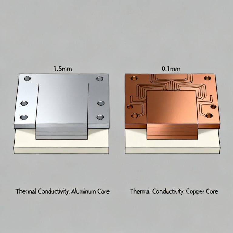
High‑power LEDs generate significant heat; High‑Tg PCB substrates (often with metal‑core) prevent degradation and extend product life.
5.7 Oil & Gas / Downhole Drilling
Electronics must operate at 200°C+; polyimide and PTFE High‑Tg PCB materials are used in this harsh environment.
6. Design Considerations for High‑Tg PCBs
6.1 Stack‑up & Layer Count
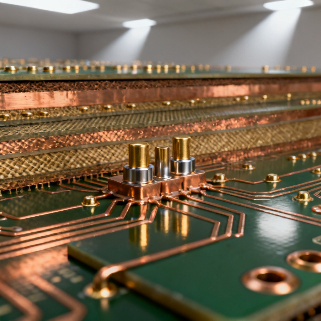
High‑Tg PCB materials can be used in multilayer boards up to 30+ layers. Ensure symmetrical stack‑up to minimize warp.
6.2 Copper Weight & Thermal Management
Use heavier copper (2 oz, 3 oz) for high‑current paths. Consider thermal vias and copper planes for heat dissipation in your High‑Tg PCB design.
6.3 Via Design
High‑Tg PCB laminates have lower Z‑axis expansion, reducing via barrel stress. Still, use filled or plugged vias for reliability in thermal cycling.
6.4 Solder Mask & Surface Finish
Standard solder masks (e.g., LPI) are compatible. For extreme temperatures, consider high‑temperature solder mask (e.g., polyimide‑based). Surface finish options include ENIG, ENEPIG, or hard gold for high‑reliability contacts.
6.5 Impedance Control
High‑Tg PCB materials have slightly different Dk values than standard FR‑4. Adjust trace width and prepreg thickness accordingly to maintain target impedance.
6.6 Manufacturing Tolerances
High‑Tg PCB materials can be more brittle; maintain sufficient annular ring and avoid sharp corners in copper features.
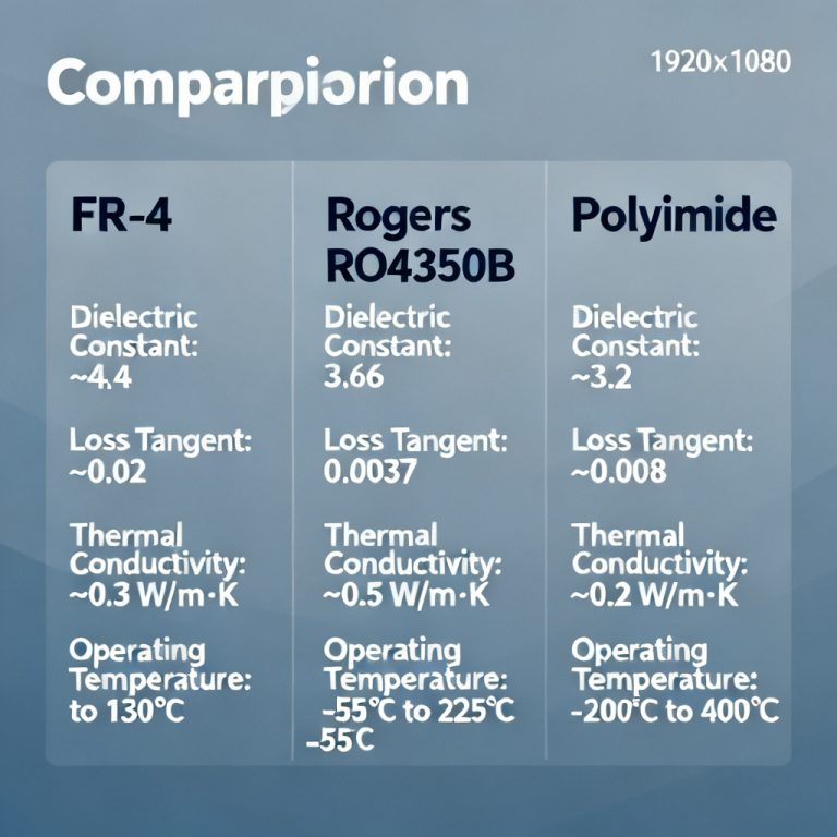
7. Comparison: High‑Tg vs Standard FR‑4 vs Other High‑Performance Laminates
| Property | Standard FR‑4 | High‑Tg FR‑4 (170°C) | Polyimide (250°C) | PTFE/Ceramic |
|---|---|---|---|---|
| Tg (°C) | 130–140 | 170–180 | 250–300 | >260 (composite) |
| CTE (Z‑axis, ppm/°C) | 50–70 | 30–50 | 20–40 | 15–30 |
| Thermal Conductivity (W/m·K) | 0.3–0.4 | 0.4–0.6 | 0.2–0.4 | 0.5–1.5 |
| Dielectric Constant (1 MHz) | 4.5–4.7 | 4.5–4.8 | 3.4–3.6 | 2.2–3.5 |
| Cost | Low | Medium | High | Very High |
| Fabrication Complexity | Standard | Standard | Specialized | Specialized |
8. Frequently Asked Questions about High‑Tg PCB
Is a higher Tg always better for a High‑Tg PCB?
Not necessarily. Higher Tg often comes with higher cost and more difficult processing. Choose the Tg that matches your maximum operating temperature + safety margin (typically 20–30°C above max).
Can I use High‑Tg FR‑4 for RF applications?
Only for low‑frequency RF (<500 MHz). For higher frequencies, use PTFE or ceramic‑filled laminates designed for High‑Tg PCB performance.
Does High‑Tg affect soldering?
Lead‑free soldering (260°C peak) is safe for High‑Tg PCB FR‑4. Polyimide can withstand multiple reflow cycles.
How do I verify Tg in a PCB supplier?
Request a DSC (Differential Scanning Calorimetry) test report per IPC‑TM‑650 2.4.25. This is the standard method for High‑Tg PCB material verification.
What is the difference between Tg and Td in High‑Tg PCB materials?
Tg (glass transition temperature) indicates when the material softens, while Td (decomposition temperature) indicates when the material chemically breaks down. Both are important for High‑Tg PCB reliability.
9. Conclusion
High‑Tg PCB materials are indispensable for modern electronics that demand thermal reliability, mechanical stability, and long service life in harsh environments. By choosing the right material—whether cost‑effective High‑Tg FR‑4, rugged polyimide, or high‑speed PTFE—you can ensure your product meets its performance and reliability targets.
Always work with a PCB manufacturer who understands the nuances of High‑Tg PCB processing, from material selection to lamination and testing. For your next project requiring high‑temperature performance, consult our engineering team to select the optimal High‑Tg PCB solution.