Flexible Rigid Flex PCB Guide Materials Stackup Bend Cycles
This comprehensive Flexible Rigid Flex PCB Guide Materials Stackup Bend Cycles manual covers materials, stackup design, and bend cycles for engineers and buyers seeking reliable, high-performance interconnect solutions. Flexible and rigid-flex PCBs are essential for modern electronics, from wearables to aerospace.
Core Topics: Substrates, adhesives, coverlays, copper foils, stiffeners, stackup rules, bend cycle testing, design best practices, and industry standards.
1. Materials for Flexible & Rigid‑Flex PCBs
1.1 Base Substrates: The Foundation of Flexibility
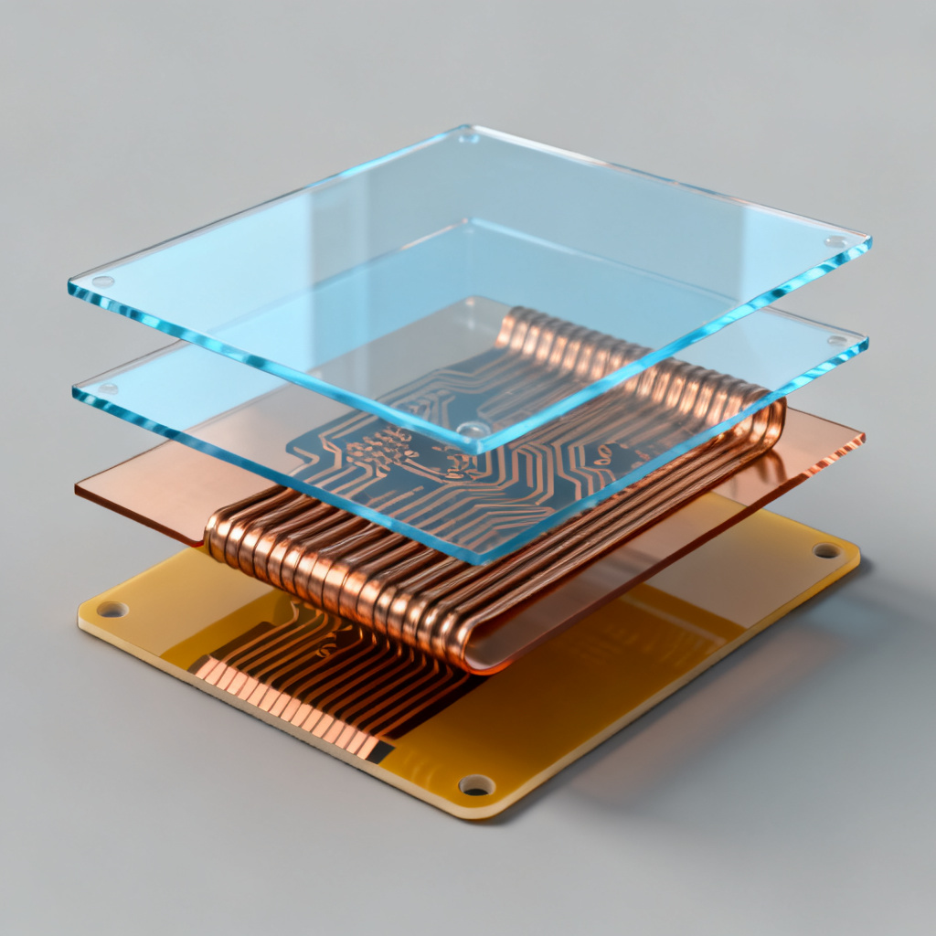
The substrate determines a flexible circuit’s mechanical and electrical performance. Polyimide (PI) is the industry standard due to its thermal stability (-269°C to +400°C), high dielectric strength, and chemical resistance. Common types include adhesive‑based polyimide (cost‑effective, lower thermal resistance) and adhesiveless polyimide (thinner, more flexible, preferred for dynamic flex). Other substrates: Polyester (PET) for low‑cost, low‑temperature uses; Liquid Crystal Polymer (LCP) for high‑frequency, low‑moisture applications; PTFE for extreme high‑frequency but expensive. Key properties: Dielectric constant (Dk ~3.2–3.5 for polyimide), dissipation factor (Df ~0.002), glass transition temperature (Tg >250°C), and coefficient of thermal expansion (CTE ~12–20 ppm/°C).
1.2 Copper Foils: Choosing the Right Conductor
Copper is the standard conductor. Rolled Annealed (RA) copper is essential for dynamic flex because its grain structure resists cracking under repeated bending. Electrodeposited (ED) copper is acceptable for static flex only. Typical thicknesses: 0.5 oz (18 µm), 1 oz (35 µm), 2 oz (70 µm). In rigid‑flex boards, flexible portions use RA copper; rigid sections may use ED copper.
1.3 Adhesives and Bonding Layers
Adhesives bond copper to substrate and coverlay. Acrylic adhesives offer good flexibility and moderate temperature resistance (up to 150°C). Epoxy adhesives provide higher temperature resistance (up to 180°C) but are less flexible. Modified epoxy and polyimide adhesives are used for high‑reliability applications (military, aerospace). Adhesive‑free constructions (adhesiveless copper‑on‑polyimide) eliminate adhesive layers, reducing thickness and improving flexibility for dynamic flex.
1.4 Coverlays and Protective Layers
Coverlays protect outer copper traces. They consist of polyimide film with an adhesive layer (acrylic or epoxy), typically 12.5 µm to 50 µm thick. Liquid photoimageable coverlays (LPI) can be used for fine‑pitch patterns but are less flexible. Solder mask is only used on rigid sections of rigid‑flex boards.
1.5 Stiffeners and Reinforcements
Stiffeners add mechanical support to connector zones or component areas. Common materials: polyimide stiffeners (moderate rigidity), FR‑4 stiffeners (high rigidity), aluminum or stainless steel stiffeners (heat dissipation). Stiffeners must not extend into flex zones to avoid stress concentration.
2. Stackup Design for Flexible & Rigid‑Flex PCBs
2.1 Flexible PCB Stackup Fundamentals
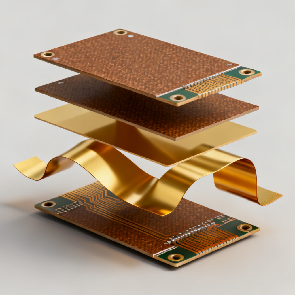
A typical flexible PCB stackup includes top coverlay, top copper layer (RA copper), polyimide substrate, optional bottom copper layer, and bottom coverlay. Key rules: Keep layers thin (<0.2 mm for dynamic flex), use symmetrical stackups, avoid vias in flex zones, and place copper on the neutral bending axis when possible.
2.2 Rigid‑Flex Stackup: Combining Rigid and Flexible Layers
Rigid‑flex PCBs integrate rigid (FR‑4) and flexible (polyimide) layers. Example stackup (4‑layer rigid + 2‑layer flex): Rigid section has solder mask, copper, FR‑4 prepreg, copper, FR‑4 core, copper, FR‑4 prepreg, copper, solder mask. Flex tail uses coverlay, copper, polyimide substrate, copper, coverlay. Critical transition zones require careful design. Common configurations: 2‑layer rigid + 1‑layer flex (low cost), 4‑layer rigid + 2‑layer flex (most common), 6‑layer rigid + 4‑layer flex (high density). Use low‑flow prepreg and no‑flow prepreg to prevent resin wicking into flex zones.
2.3 Controlled Impedance in Flexible Circuits
For high‑speed signals (USB, HDMI, RF), controlled impedance is critical. Microstrip and stripline configurations are possible on flex. Impedance tolerance is typically ±10% for flex, but ±5% is achievable with careful material selection. Polyimide’s Dk varies with frequency and moisture; for critical designs, use LCP or specify material Dk at operating frequency.
2.4 Via Types and Their Impact on Flexibility
Through‑hole vias are not recommended in dynamic flex zones because the copper barrel cracks. Blind and buried vias are used only in rigid sections. Staggered vias distribute stress better than stacked vias. Via‑in‑pad should be avoided in flex zones. For dynamic flex, use flexible vias with larger annular rings and thinner copper.
3. Bend Cycles and Flex Life
3.1 Understanding Bend Cycles
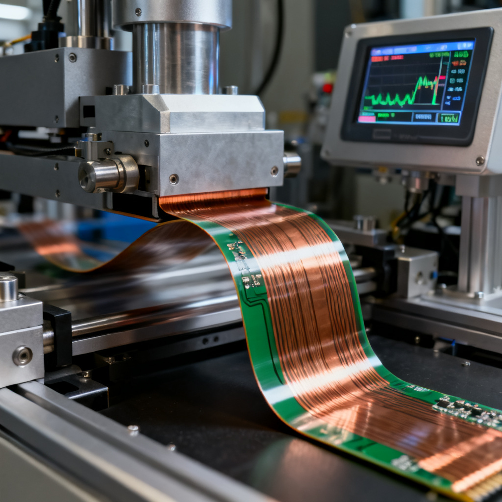
Bend cycle life is the number of times a flexible circuit can be bent to a given radius before failure (20% increase in resistance per IPC‑6013). Key parameters: Bend radius (minimum 6× total thickness for dynamic flex, 10× recommended), bend angle, copper thickness (thinner = more cycles), copper type (RA copper lasts 10–100× more than ED copper), adhesive vs. adhesiveless (adhesiveless lasts 2–5× longer), temperature (life halves every 10°C above 85°C), and humidity (can reduce life by 30–50%).
3.2 IPC Bend Cycle Testing Standards
IPC‑6013 defines dynamic flex test (repeated bending at 1 cycle/second), static flex test (bent and held for specified time), and flex‑to‑install test (one or few bends). Typical requirements: Consumer electronics: 10,000–50,000 cycles; Automotive: 100,000–500,000 cycles; Medical: 1,000–10,000 cycles; Aerospace: 10,000–100,000 cycles.
3.3 How to Maximize Bend Cycle Life
Design recommendations: Use RA copper exclusively for dynamic flex; choose adhesiveless polyimide; minimize total flex thickness (<0.15 mm for high‑cycle applications); increase bend radius (R > 10× thickness); avoid sharp corners on traces (use 45° or curved routing); stagger traces in multilayer flex; add strain relief at rigid‑flex transitions (teardrop pads, larger annular rings); use flexible coverlay instead of solder mask; avoid plating in flex zones (ENIG acceptable but adds thickness). Manufacturing: Control etching to avoid stress risers; use low‑stress lamination; test flex life on prototypes.
3.4 Bend Cycle Calculation and Simulation
Estimate flex life using IPC‑2221A formula: Dynamic flex life (cycles) = k × (R/t)², where R = bend radius, t = total flex thickness, k is material constant (e.g., 1000 for RA copper with adhesiveless polyimide, 200 for ED copper with adhesive). Example: 0.1 mm thick flex, RA copper, adhesiveless polyimide, 1 mm radius → 100,000 cycles. Finite Element Analysis (FEA) tools (Ansys, COMSOL) simulate stress distribution for critical applications.
4. Design Rules and Best Practices

4.1 Layout Guidelines for Flexible Circuits
Use wider traces (0.2 mm minimum) for dynamic flex; fine lines (<0.1 mm) for static flex only. Balance copper across layers to prevent warpage; use cross‑hatch patterns for large copper areas. Avoid sharp transitions between flex and rigid (use gradual taper over 2 mm). Keep components off flex tails; use stiffeners under connectors.
4.2 Common Rigid‑Flex Design Mistakes
Insufficient flex tail length (minimum 2 × bend radius + 5 mm); resin wicking into flex zone (use no‑flow prepreg); placing vias in bend area; ignoring thermal management (polyimide has low thermal conductivity); over‑specifying bend cycles (increases cost unnecessarily).
4.3 Manufacturing Process Overview
Steps: Material preparation → drilling (laser for small vias, mechanical for larger) → plating (electroless copper then electrolytic) → etching → coverlay application → lamination (rigid‑flex) → stiffener attachment → final testing (continuity, impedance, flex life).
5. Applications and Industry Standards
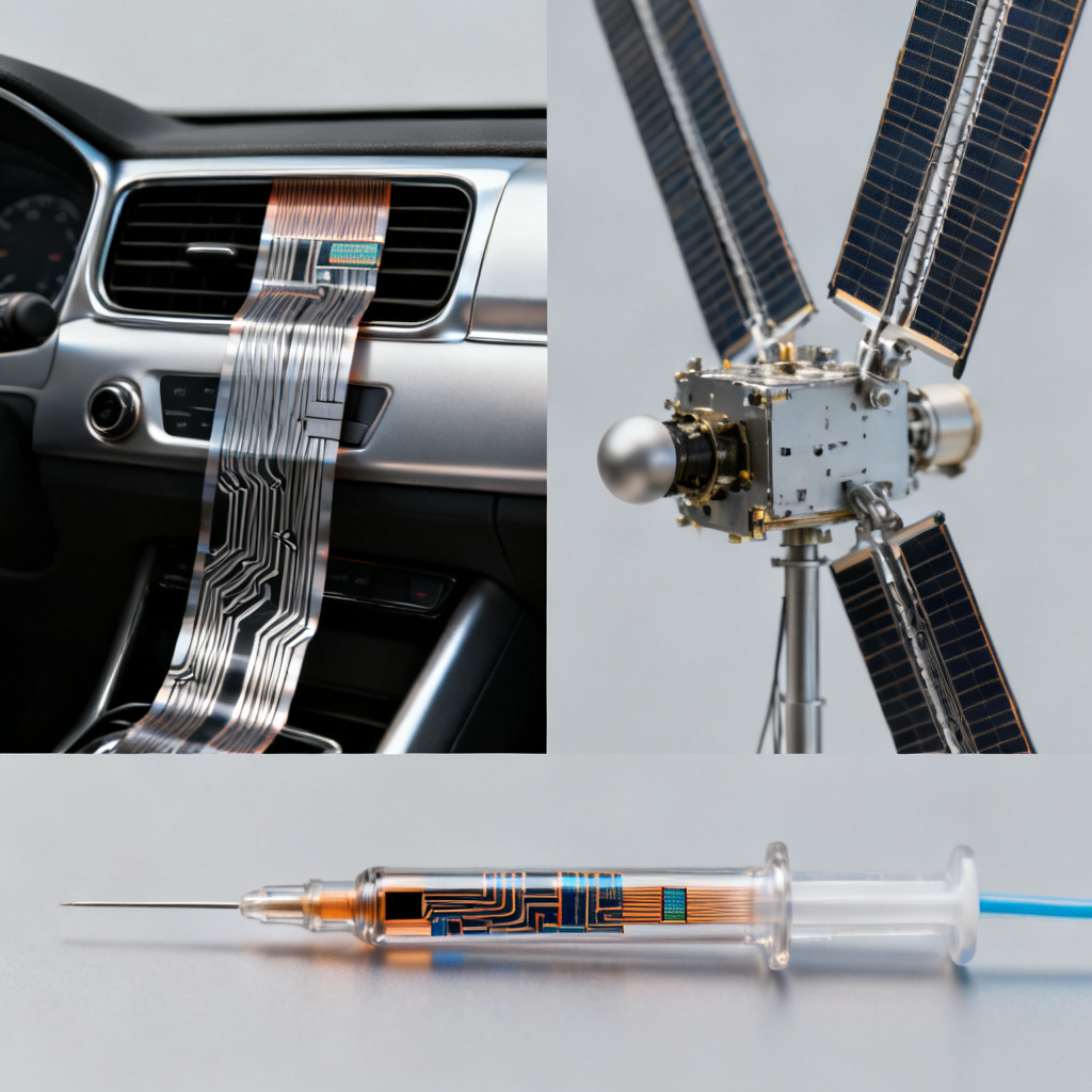
5.1 Typical Applications
| Industry | Application | Key Requirements |
|---|---|---|
| Consumer Electronics | Smartphone hinges, camera modules, foldable displays | High cycle life (>50k), thin profile |
| Automotive | Airbag sensors, seat controls, infotainment | Temperature range -40°C to +125°C, high reliability |
| Medical | Catheters, hearing aids, pacemakers | Biocompatibility, ultra‑thin, low cost |
| Aerospace | Satellite deployables, avionics | Extreme temperature, radiation resistance, long life |
| Industrial | Robotics, sensors, LED lighting | Flexibility, chemical resistance |
5.2 Relevant Standards
IPC‑6013 (performance specification for flexible and rigid‑flex boards, Classes 1, 2, 3), IPC‑2223 (design guide), IPC‑4101 (base materials), MIL‑PRF‑31032 (military standard), UL 796 (safety standard).
6. FAQ: Flexible & Rigid‑Flex PCB Guide
What is the difference between static and dynamic flex in a Flexible & Rigid‑Flex PCB?
Static flex refers to bending a flexible circuit during installation only (few cycles), while dynamic flex involves repeated bending during operation (thousands to millions of cycles). Dynamic flex requires RA copper and adhesiveless polyimide for longer life.
What is the minimum bend radius for a Flexible & Rigid‑Flex PCB?
The minimum bend radius is typically 6× the total flex thickness for dynamic applications, but 10× is recommended for high reliability. For static flex, 3× thickness may be acceptable.
How do I calculate bend cycle life for a Flexible & Rigid‑Flex PCB?
Use the IPC‑2221A formula: Dynamic flex life (cycles) = k × (R/t)², where R is bend radius, t is total flex thickness, and k is a material constant (e.g., 1000 for RA copper with adhesiveless polyimide).
Why is RA copper preferred for flexible circuits?
Rolled Annealed (RA) copper has a grain structure that withstands repeated bending without cracking, making it essential for dynamic flex applications. Electrodeposited (ED) copper is more prone to cracking under flex.
What materials are best for high‑frequency Flexible & Rigid‑Flex PCBs?
Liquid Crystal Polymer (LCP) offers ultra‑low moisture absorption, excellent high‑frequency performance (low Dk/Df), and high temperature resistance. Polyimide is also used but has higher moisture sensitivity.
Conclusion
Flexible and rigid‑flex PCBs offer unparalleled design freedom, but success depends on careful material selection, optimized stackup design, and rigorous bend cycle testing. Key takeaways: Use adhesiveless polyimide and RA copper for dynamic flex; design symmetrical stackups with thin flex sections; calculate bend cycle life using IPC formulas; avoid vias and sharp corners in flex zones; partner with an experienced manufacturer.
For your next Flexible & Rigid‑Flex PCB project, consult our engineering team for design optimization and volume production support.
Comparison: Flexible vs. Rigid‑Flex PCBs
| Feature | Flexible PCB | Rigid‑Flex PCB |
|---|---|---|
| Structure | Entirely flexible layers | Combination of rigid and flexible layers |
| Bend Cycles | Up to 500,000 cycles with RA copper | Limited by rigid‑flex transition zone |
| Component Mounting | Requires stiffeners | Components on rigid sections |
| Cost | Lower for simple designs | Higher due to complex lamination |
| Reliability | High for dynamic flex | High for mixed‑technology designs |
Glossary of Terms
- Polyimide (PI): A high‑temperature polymer used as flexible substrate.
- RA Copper: Rolled Annealed copper, grain structure optimized for flexing.
- ED Copper: Electrodeposited copper, columnar grain structure, less flexible.
- Coverlay: Protective polyimide film with adhesive for outer traces.
- Stiffener: Rigid material (FR‑4, aluminum) added for mechanical support.
- Bend Radius: The radius of curvature a flexible circuit can withstand.
- Dynamic Flex: Repeated bending during operation.
- Static Flex: Bending during installation only.