Thermal Parameters Tg Td CTE Thermal Conductivity
Understanding Thermal Parameters Tg Td CTE Thermal Conductivity is essential for reliable PCB performance in high-power and high-frequency applications. This guide synthesizes trusted industry knowledge to help you select optimal materials for your B2B PCB manufacturing needs.
- 1. Glass Transition Temperature (Tg)
- 2. Decomposition Temperature (Td)
- 3. Coefficient of Thermal Expansion (CTE)
- 4. Thermal Conductivity (k)
- 5. Interrelationship of Tg, Td, CTE, and Thermal Conductivity
- 6. How to Specify These Parameters in Your PCB Order
- 7. Common Mistakes and How to Avoid Them
- 8. Conclusion: Selecting the Right Material for Your Application
- FAQ
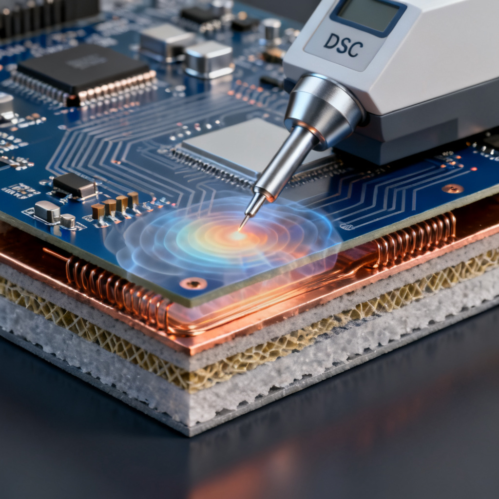
1. Glass Transition Temperature (Tg): The Softening Point of Your PCB
Glass Transition Temperature (Tg) is the temperature at which a PCB substrate transitions from a rigid, glass-like state to a softer, rubbery state. Below Tg, the material maintains its mechanical integrity; above it, the resin expands significantly, leading to dimensional instability, z-axis expansion, and potential via cracking.
Why Tg Matters for Thermal Parameters – Tg, Td, CTE, Thermal Conductivity
High-Tg materials (≥170°C) are used for lead-free soldering, automotive, and high-reliability applications. They resist warpage during reflow and provide better thermal cycling performance. Standard Tg (130–150°C) is suitable for consumer electronics with moderate thermal demands. If operating temperature exceeds Tg, the PCB experiences rapid CTE increase (especially in the Z-axis), causing barrel cracks in plated through-holes and delamination.
Industry Standards and Testing for Thermal Parameters – Tg, Td, CTE, Thermal Conductivity
Tg is measured via DSC (Differential Scanning Calorimetry) or TMA (Thermomechanical Analysis) per IPC-TM-650. Common high-Tg laminates include:
- FR-4 High Tg (170°C): Balance of cost and performance.
- Polyimide (260°C Tg): For extreme environments.
- BT Epoxy (180–200°C): For IC substrates and RF applications.
Key Takeaway: Always select a Tg at least 25°C above your maximum operating temperature to avoid performance degradation.
2. Decomposition Temperature (Td): When the PCB Begins to Chemically Break Down
Decomposition Temperature (Td) is the temperature at which the PCB laminate loses 5% of its mass due to chemical decomposition. Unlike Tg (a physical change), Td indicates the onset of permanent material failure.
Why Td is Critical in Thermal Parameters – Tg, Td, CTE, Thermal Conductivity
Lead-free soldering (260°C peak) requires materials with Td ≥ 325°C to survive multiple reflow cycles without outgassing or delamination. High Td materials resist combustion and reduce toxic emissions. A higher Td correlates with better long-term thermal stability and lower risk of “measling” (white spots) or “crazing.”
How Td is Measured
Using TGA (Thermogravimetric Analysis), the decomposition onset is defined as the temperature at 5% weight loss. Typical values:
- Standard FR-4: Td ≈ 305–315°C
- High-Tg FR-4: Td ≈ 325–340°C
- Polyimide: Td > 400°C
Expert Insight: For designs requiring multiple lead-free reflow cycles (e.g., BGAs, QFNs), specify Td ≥ 340°C to ensure no volatile release during assembly.
3. Coefficient of Thermal Expansion (CTE): Managing Dimensional Changes Under Heat
Coefficient of Thermal Expansion (CTE) measures how much a material expands per degree Celsius. In PCBs, three axes matter:
- X-Y CTE (In-plane): Typically 12–18 ppm/°C for standard FR-4. Mismatch with copper (17 ppm/°C) causes stress on traces.
- Z-Axis CTE (Through-thickness): Much higher (50–100 ppm/°C below Tg, 200–300 ppm/°C above Tg). This is the primary cause of via barrel cracking.
Why CTE is a Reliability Killer in Thermal Parameters – Tg, Td, CTE, Thermal Conductivity
Plated Through-Hole (PTH) stress occurs when Z-axis CTE is high, leading to “knee cracking” or “barrel separation.” CTE mismatch between PCB and ceramic components (e.g., BGAs) causes solder ball cracking after thermal cycling.
How to Control CTE
- Fillers: Silica-filled laminates reduce Z-axis CTE to 30–50 ppm/°C.
- Low-CTE Laminates: For HDI and RF applications, choose materials with X-Y CTE matched to copper (e.g., Rogers 4350B: 14 ppm/°C).
- IPC Standards: For high-reliability designs, specify Z-axis CTE < 50 ppm/°C below Tg and < 200 ppm/°C above Tg.
Practical Rule: For boards with multiple layers (≥10), use low-Z-axis-CTE materials to prevent via failures during assembly and field operation.
4. Thermal Conductivity (k): Moving Heat Away from Hot Spots
Thermal conductivity (k) (measured in W/m·K) quantifies a material’s ability to conduct heat. Standard FR-4 has poor thermal conductivity (~0.3 W/m·K), which is why thermal management is a primary design constraint.
Why Thermal Conductivity Matters for Thermal Parameters – Tg, Td, CTE, Thermal Conductivity
High-power components like LEDs, IGBTs, and power amplifiers generate heat that must be dissipated to prevent junction temperature rise. Higher k materials (e.g., metal-core PCBs at 1–3 W/m·K) reduce thermal gradients and improve reliability. For multilayer boards, thermal vias and copper planes enhance effective conductivity.
Material Options by Thermal Conductivity
| Material Type | Typical k (W/m·K) | Application |
|---|---|---|
| Standard FR-4 | 0.3 | Low-power designs |
| High-Thermal FR-4 (filled) | 0.6–1.0 | Mid-power LED drivers |
| Aluminum IMS (Insulated Metal Substrate) | 1.5–3.0 | High-power LEDs, motor controls |
| Ceramic (Al₂O₃, AlN) | 20–170 | RF amplifiers, laser diodes |
How to Enhance Thermal Performance Without Changing Laminate
- Copper Thickness: Use 2 oz or 3 oz copper for power planes.
- Thermal Vias: Arrays of filled vias under components (e.g., 0.3mm diameter, 1.0mm pitch) can increase effective k by 5–10x.
- Thermal Interface Materials (TIMs): Gap pads or phase-change materials between PCB and heatsink.
Engineer’s Tip: For designs with > 2W/cm² heat flux, consider metal-core PCBs or embedded copper coin technology.
5. Interrelationship of Tg, Td, CTE, and Thermal Conductivity
These thermal parameters – Tg, Td, CTE, Thermal Conductivity – are not independent. A material with high Tg often has higher Td (better decomposition resistance), lower Z-axis CTE below Tg (less expansion), but potentially lower thermal conductivity (if not filled).
Example: A high-Tg FR-4 (Tg 170°C, Td 330°C) may have Z-axis CTE of 40 ppm/°C below Tg but 250 ppm/°C above Tg. To mitigate this, designers often pair it with thermal vias and copper planes to manage both expansion and heat.
| Laminate | Tg (°C) | Td (°C) | Z-CTE (ppm/°C) | k (W/m·K) |
|---|---|---|---|---|
| Standard FR-4 | 135 | 310 | 60 (below Tg) | 0.3 |
| High-Tg FR-4 | 170 | 340 | 50 (below Tg) | 0.4 |
| Polyimide | 260 | 400 | 40 (below Tg) | 0.25 |
| Rogers 4350B | 280 | 390 | 25 (Z-axis) | 0.62 |
| Aluminum IMS | N/A | N/A | 20 (Z-axis) | 2.0 |
6. How to Specify These Parameters in Your PCB Order
To ensure your manufacturer delivers a reliable product, include these specifications in your fabrication drawing:
- Tg: Minimum 170°C for lead-free assembly; 130°C for standard.
- Td: Minimum 325°C for single reflow; 340°C for multiple reflow.
- CTE (Z-axis): < 50 ppm/°C below Tg; < 200 ppm/°C above Tg.
- Thermal Conductivity: Specify if > 0.5 W/m·K is required; otherwise, rely on copper.
- Testing: Request DSC/TGA reports for Tg/Td, TMA for CTE, and ASTM D5470 for thermal conductivity.
Pro Tip: For prototypes, ask for a “thermomechanical characterization” report to validate the laminate batch.
7. Common Mistakes and How to Avoid Them
- Mistake 1: Assuming high Tg automatically means high Td. (Reality: Some high-Tg materials have lower Td due to different resin systems.)
- Mistake 2: Ignoring Z-axis CTE above Tg. (Reality: Even short excursions above Tg during reflow can cause micro-cracks.)
- Mistake 3: Overlooking thermal conductivity for high-layer-count boards. (Reality: Heat trapped between layers can cause hot spots.)
- Mistake 4: Using thermal vias without proper plating. (Reality: Unfilled vias have poor thermal transfer; use copper-filled or silver-filled vias.)
8. Conclusion: Selecting the Right Material for Your Application
The four thermal parameters – Tg, Td, CTE, and Thermal Conductivity – form a decision matrix for any PCB design. For general-purpose boards, standard FR-4 with Tg 135°C and Td 310°C suffices. For automotive, aerospace, or industrial applications, specify high-Tg (170°C+), high-Td (340°C+), low Z-CTE (< 50 ppm/°C), and consider metal-core or ceramic laminates for thermal conductivity.
At Sensormass we offer a full range of laminates with certified thermal data. Our engineering team can help you select the optimal material for your specific operating conditions, ensuring your PCB performs reliably from prototype to mass production.
Request a free thermal parameter analysis for your next project—upload your Gerber files and get a material recommendation within 24 hours.
FAQ: Thermal Parameters – Tg, Td, CTE, Thermal Conductivity
What is the difference between Tg and Td in thermal parameters?
Tg (Glass Transition Temperature) is a physical change where the PCB substrate softens, while Td (Decomposition Temperature) is a chemical breakdown point where the material loses mass. Both are critical thermal parameters – Tg, Td, CTE, Thermal Conductivity for reliability.
How does CTE affect PCB reliability in thermal management?
High Z-axis CTE causes via barrel cracking and solder joint fatigue, especially above Tg. Controlling CTE is essential for thermal parameters – Tg, Td, CTE, Thermal Conductivity to ensure long-term performance.
Why is thermal conductivity important for high-power PCBs?
Thermal conductivity (k) determines how efficiently heat is dissipated from hot spots. Low k values (like standard FR-4 at 0.3 W/m·K) can lead to overheating, so selecting materials with higher k is key in thermal parameters – Tg, Td, CTE, Thermal Conductivity.
Can I use standard FR-4 for lead-free soldering?
Standard FR-4 has Td around 310°C, which may not survive multiple lead-free reflow cycles. For lead-free assembly, specify high-Tg FR-4 with Td ≥ 325°C to ensure thermal parameters – Tg, Td, CTE, Thermal Conductivity are met.
How do I request thermal parameter data from a PCB manufacturer?
Request DSC/TGA reports for Tg/Td, TMA for CTE, and ASTM D5470 for thermal conductivity. Always verify these thermal parameters – Tg, Td, CTE, Thermal Conductivity before production.