Prepreg and Core Resin Content Flow Dk Df
In the world of high-reliability printed circuit boards (PCBs), understanding Prepreg and Core Resin Content Flow Dk Df materials is not optional—it is foundational. This prepreg and core guide synthesizes expert knowledge from top industry references to give you a complete, actionable understanding of resin content, resin flow, and Dk/Df (dielectric constant and dissipation factor) characteristics.
1. What Are Prepreg and Core? Definitions and Roles
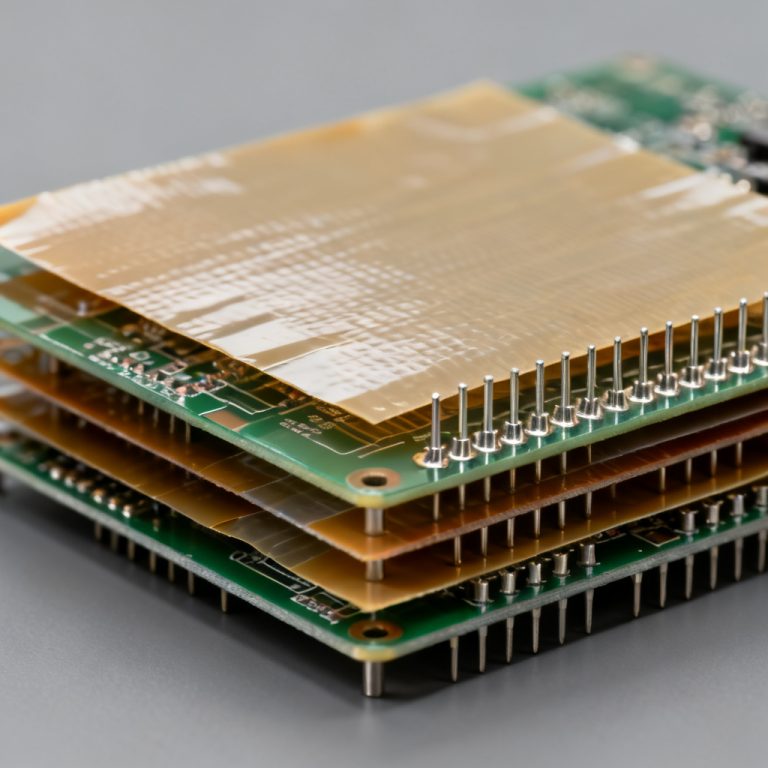
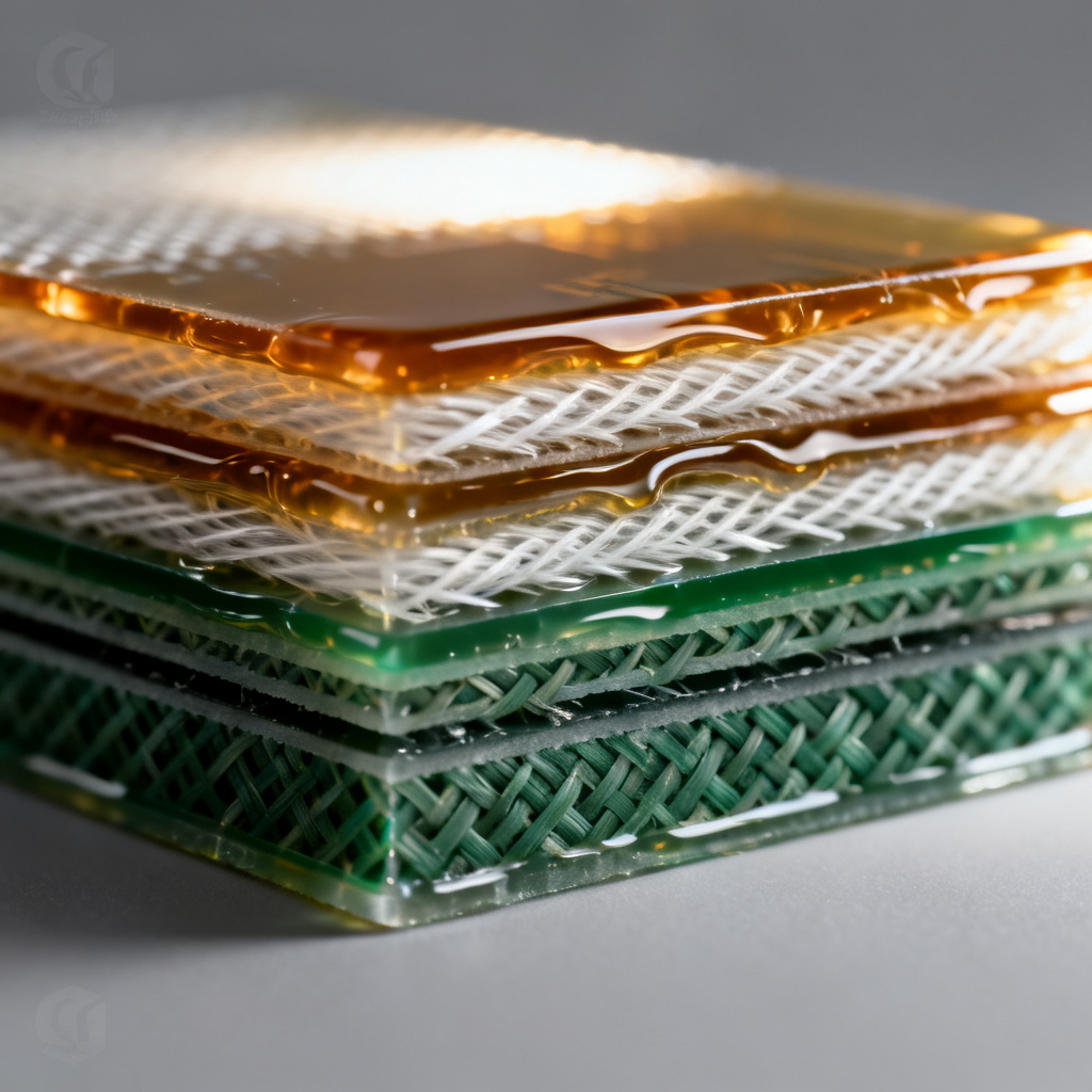
Core (also called laminate) is a rigid, fully cured sheet of epoxy resin reinforced with glass fiber fabric (e.g., FR-4). It serves as the base substrate for inner layers and provides structural rigidity. Core materials are produced with a specific glass transition temperature (Tg) and copper foil on one or both sides.
Prepreg (pre-impregnated) is a sheet of glass fiber fabric partially cured (B-stage) with resin. It is used as the bonding layer between cores and copper foils during lamination. Prepreg melts and flows under heat and pressure, then fully cures to form a solid dielectric. It is the key variable in controlling final thickness, impedance, and dielectric properties.
Key difference: Core is fully cured and rigid; prepreg is semi-cured and flows during lamination. This distinction drives their respective roles in stack-up design.
2. Prepreg and Core – Resin Content: The Master Variable
Resin content is the weight percentage of resin in the prepreg and core material. It directly influences:
- Dielectric constant (Dk) – Higher resin content lowers Dk (since resin has lower Dk than glass).
- Dissipation factor (Df) – Resin dominates losses; higher resin content can increase Df depending on resin type.
- Flow characteristics – More resin means higher flow, which affects gap filling and thickness control.
- Mechanical properties – Higher resin content improves bonding strength but may reduce dimensional stability.
2.1 Resin Content Ranges and Standard Values for Prepreg and Core
According to IPC-4101 and common supplier datasheets (e.g., Isola, Rogers, Panasonic), typical resin content for prepregs ranges from 42% to 68% by weight. For cores, resin content is generally lower (40–55%) because they are fully cured and must maintain rigidity.
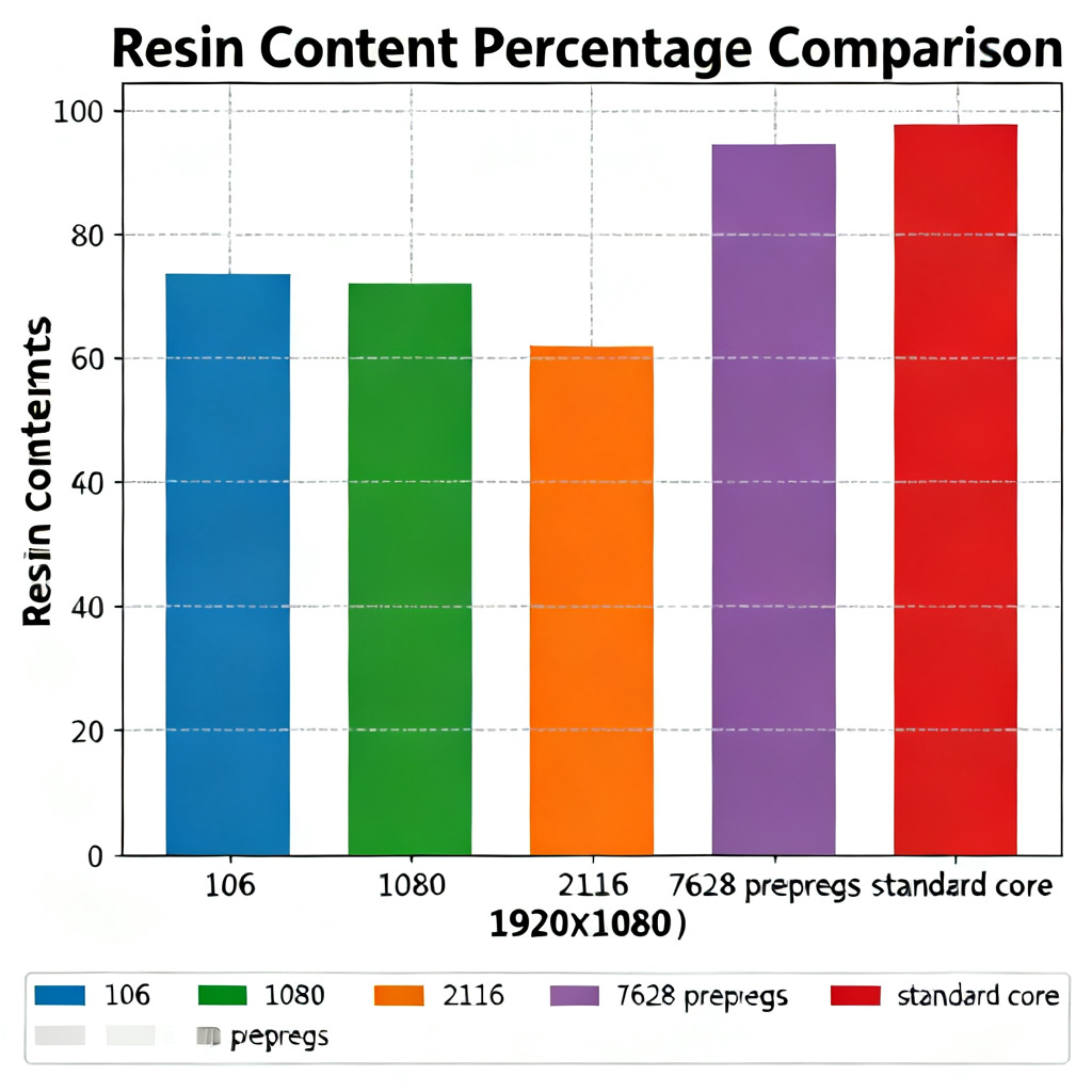
| Prepreg and Core Style | Typical Resin Content (%) | Common Use Case |
|---|---|---|
| 106 prepreg | ~68% | Thin layers, impedance tuning |
| 1080 prepreg | ~62% | General high-flow applications |
| 2116 prepreg | ~55% | Balanced flow and thickness |
| 7628 prepreg | ~42% | Thick, stable layers |
| Standard FR-4 core | 45–50% | Base substrate |
2.2 How Resin Content Affects Dk and Df in Prepreg and Core
The dielectric constant of a prepreg and core is a weighted average of the glass fiber (Dk ≈ 6.0–6.5) and the resin (Dk ≈ 3.0–4.5 for epoxy). Therefore:
- High resin content (e.g., 106 prepreg) → Lower overall Dk (e.g., 3.8–4.2 at 1 GHz)
- Low resin content (e.g., 7628 prepreg) → Higher overall Dk (e.g., 4.5–5.0 at 1 GHz)
Similarly, Df is dominated by resin losses. Standard FR-4 epoxy has Df ≈ 0.015–0.020 at 1 GHz. High-resin prepregs can have slightly higher Df due to higher resin volume, but the effect is small compared to resin type (e.g., low-loss resins like Megtron 6 have Df < 0.005).
Critical insight: For impedance-controlled designs, you must account for the actual resin content of the prepreg layer—not just the glass style—because resin content changes the effective Dk.
3. Prepreg and Core – Resin Flow: The Manufacturing Critical Parameter
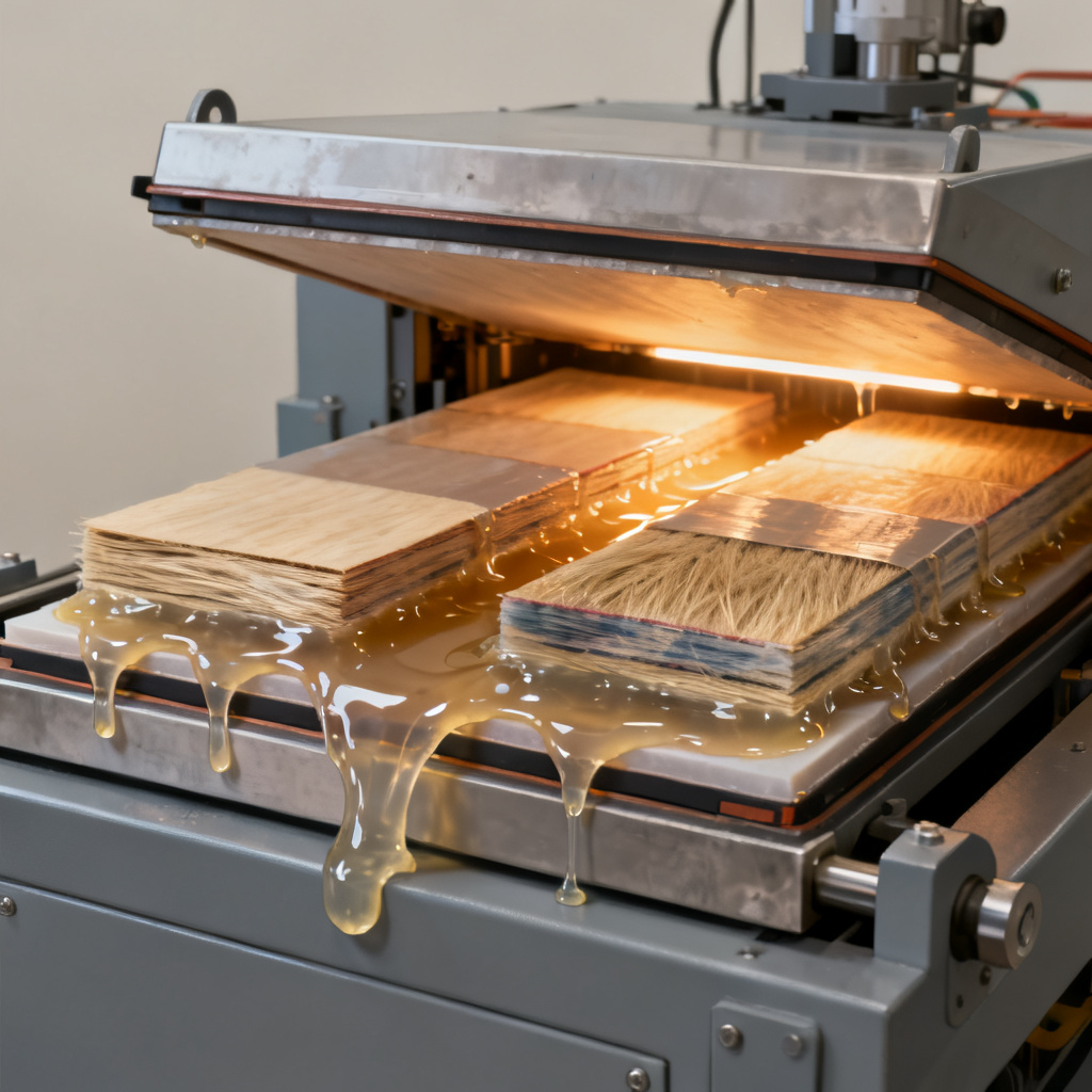
Resin flow is the movement of molten prepreg resin during lamination. It is measured as a percentage of weight change under controlled conditions (IPC-TM-650 method 2.3.17.1). Proper flow ensures:
- Complete filling of gaps between circuit traces and around vias.
- Void-free bonding between layers.
- Uniform final dielectric thickness.
3.1 Factors Influencing Resin Flow in Prepreg and Core
- Resin content – Higher resin content = higher flow potential.
- Resin viscosity – Lower viscosity (e.g., standard epoxy) flows more than high-viscosity (e.g., high-Tg, low-loss resins).
- Glass style – Open weaves (e.g., 106) allow more flow than dense weaves (e.g., 7628).
- Lamination parameters – Higher temperature, pressure, and longer dwell time increase flow.
- Prepreg age and storage – Outgassing or moisture absorption reduces flow.
3.2 Flow Ranges and Selection Guidelines for Prepreg and Core
| Prepreg and Core Style | Typical Flow (%) | Application Note |
|---|---|---|
| 106 prepreg | 30–50% | High flow for thin layers, gap filling |
| 1080 prepreg | 25–40% | General purpose |
| 2116 prepreg | 15–25% | Balanced flow |
| 7628 prepreg | 10–20% | Low flow for stable thickness |
Selection rules:
- Use high-flow prepregs (106, 1080) when filling deep gaps (e.g., around large copper pours) or when thin dielectric layers are needed.
- Use low-flow prepregs (7628) for thick, stable layers where thickness control is critical.
- For hybrid stack-ups (e.g., FR-4 with high-speed materials), match flow characteristics to avoid resin starvation or excess.
3.3 Controlling Flow in Manufacturing of Prepreg and Core
To prevent resin starvation (too much flow) or voiding (too little flow), fabricators use:
- Pre-bonding (pressing at low temperature to initiate flow before full cure)
- Controlled lamination cycle (ramp-up temperature, dwell time, and pressure profile)
- Flow stops (e.g., using prepreg with lower flow on outer layers)
Expert tip: For designs with mixed prepreg types, always simulate flow using supplier models (e.g., Isola FlowSim) to predict final thickness and resin distribution.
4. Prepreg and Core – Dk and Df: The Electrical Performance Metrics
Dk (dielectric constant) and Df (dissipation factor) determine signal speed, impedance, and loss in high-frequency circuits. They are frequency-dependent and temperature-dependent.
4.1 Dk: Dielectric Constant in Prepreg and Core
Dk is the ratio of the capacitance of a material to that of vacuum. It affects:
- Impedance – Higher Dk lowers characteristic impedance for a given trace geometry.
- Signal velocity – Slower in higher Dk materials (v = c / √Dk).
- Wavelength – Shorter in higher Dk materials.
Typical Dk values (at 1 GHz, conditioned per IPC-TM-650):
- Standard FR-4: 4.2–4.5 (varies with resin content)
- High-Tg FR-4: 4.3–4.7
- Low-loss materials (e.g., Rogers 4350B): 3.48 (stable)
- Polyimide: 3.5–4.0
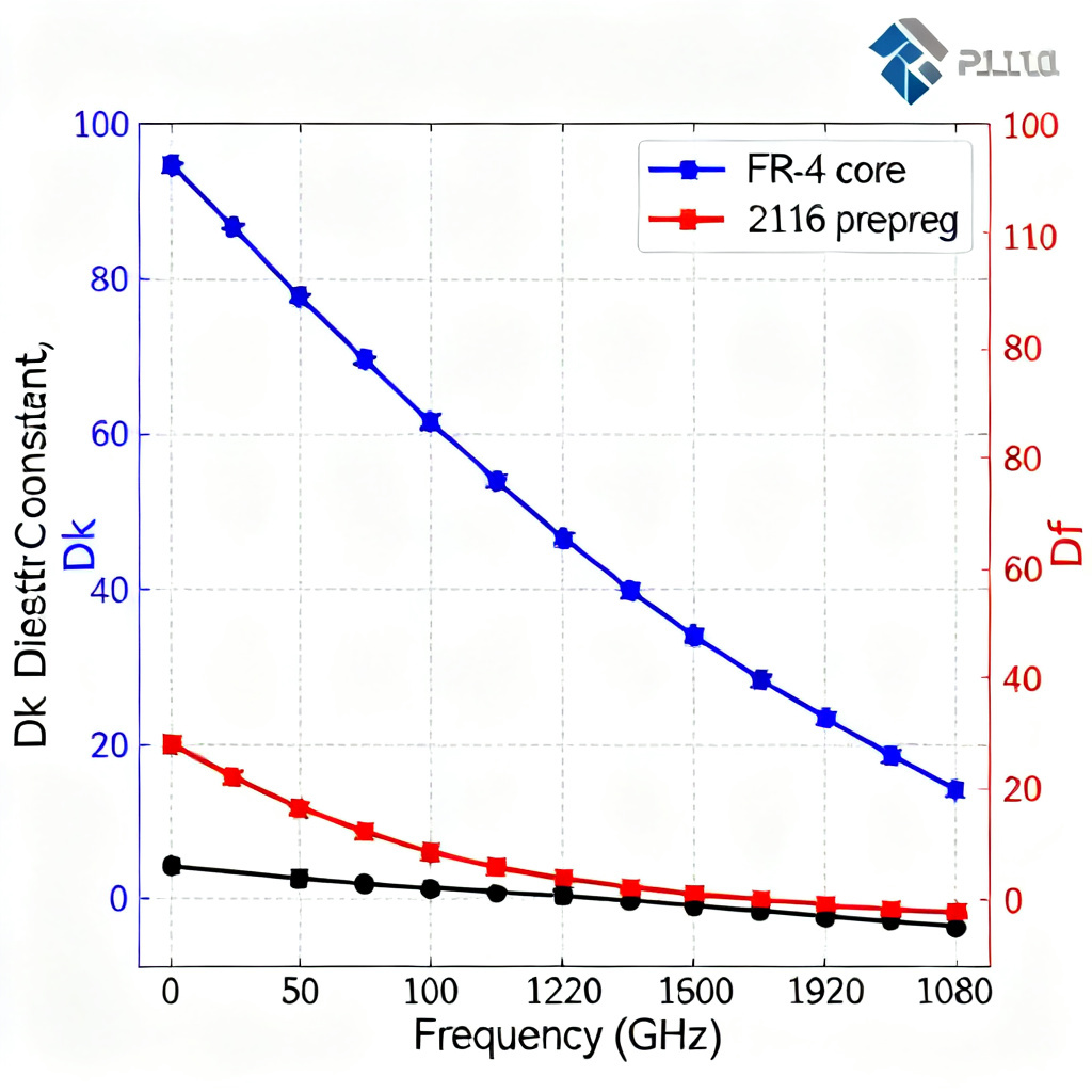
Important: Dk is not constant. It decreases with increasing frequency (due to polarization lag) and increases with temperature. For accurate modeling, use the Dk value at your operating frequency.
4.2 Df: Dissipation Factor (Loss Tangent) in Prepreg and Core
Df measures energy loss as heat in the dielectric. Lower Df means less signal attenuation. It is critical for:
- High-frequency circuits (RF, microwave, 5G)
- High-speed digital (high bit rates, low jitter)
- Power integrity (less dielectric heating)
Typical Df values (at 1 GHz):
- Standard FR-4: 0.015–0.020
- High-Tg FR-4: 0.012–0.018
- Low-loss FR-4 (e.g., Isola 370HR): 0.010–0.014
- Ultra-low-loss (e.g., Megtron 6, Rogers 3003): 0.002–0.005
4.3 How Prepreg and Core Dk/Df Differ
Because prepreg and core have different resin content and glass volume, their Dk/Df values differ even for the same material family:
- Core: More glass, less resin → higher Dk, slightly lower Df (glass has lower loss than epoxy).
- Prepreg: More resin, less glass → lower Dk, slightly higher Df.
Example: For a standard FR-4 system:
- Core (1.6 mm thick, 45% resin): Dk ≈ 4.5, Df ≈ 0.015
- 2116 prepreg (0.1 mm, 55% resin): Dk ≈ 4.2, Df ≈ 0.018
Critical for stack-up design: Use the correct Dk/Df for each layer type in your impedance calculator. Many tools default to core values, which can cause errors for prepreg-only layers.
5. Practical Stack-Up Design Guidelines for Prepreg and Core
5.1 Selecting Prepreg and Core Combinations
- Symmetry: Always balance stack-up around the center to prevent warpage.
- Copper weight: Thicker copper (2 oz or more) requires higher-flow prepregs to fill gaps.
- Impedance tolerance: For tight impedance control (±5%), use thin prepregs (106, 1080) with known resin content.
- Thermal management: For high-Tg designs, use compatible prepreg and core (same resin system).
5.2 Calculating Final Dielectric Thickness for Prepreg and Core
Final thickness depends on:
- Prepreg resin content – Higher resin = thicker final layer (after lamination, some resin flows out).
- Copper thickness and pattern – Thick copper or dense traces reduce effective thickness.
- Lamination pressure – Higher pressure reduces final thickness.
Use supplier-provided flow models or thickness calculators (e.g., Isola, Rogers, or IPC-2221) to predict final thickness. A common rule: final prepreg thickness is about 80–90% of the raw prepreg thickness for standard materials.
5.3 Avoiding Common Pitfalls with Prepreg and Core
- Resin starvation: Using low-flow prepregs with thick copper or large gaps → voids.
- Thickness variation: Mixing high-flow and low-flow prepregs in the same stack-up → uneven layers.
- Dk mismatch: Assuming core and prepreg have the same Dk → impedance errors.
- Over-specifying: Using ultra-low-loss materials when not needed → cost overruns.
6. Testing and Verification of Prepreg and Core
To ensure your prepreg and core materials meet specifications, use these standard tests (per IPC-TM-650):
- Resin content: Method 2.3.16 (burn-off or chemical extraction)
- Resin flow: Method 2.3.17.1 (flow percentage under controlled press)
- Dk/Df: Method 2.5.5.5 (stripline resonator at 1–10 GHz) or Method 2.5.5.1 (capacitance method)
- Tg: Method 2.4.25 (DSC) or 2.4.24 (TMA)
- Dimensional stability: Method 2.2.4 (x-y shrinkage)
For production, request certificates of compliance from your laminator and perform incoming inspection on critical parameters.
7. Conclusion: Mastering Prepreg and Core for High-Performance PCBs
Understanding prepreg and core—specifically their resin content, flow, and Dk/Df—is essential for designing reliable, high-performance PCBs. Key takeaways:
- Resin content dictates Dk, Df, and flow; choose prepreg styles (106, 1080, 2116, 7628) based on your electrical and manufacturing needs.
- Resin flow must be matched to copper weight and pattern to avoid voids or thickness variation.
- Dk and Df differ between core and prepreg; always use layer-specific values in impedance calculations.
- Test and verify using IPC methods to ensure material performance.
By applying these principles, you can optimize your PCB stack-up for signal integrity, manufacturability, and cost efficiency. For custom stack-up design support or material selection, contact our engineering team—we specialize in high-reliability PCB fabrication with full material traceability.
Frequently Asked Questions about Prepreg and Core
What is the difference between prepreg and core in PCB manufacturing?
Prepreg and core differ primarily in cure state: core is fully cured and rigid, while prepreg is semi-cured and flows during lamination. This affects how they are used in stack-up design, with core providing structure and prepreg acting as a bonding layer.
How does resin content affect Dk in prepreg and core?
Higher resin content in prepreg and core lowers the overall Dk because resin has a lower dielectric constant (≈3.0–4.5) than glass fiber (≈6.0–6.5). This is critical for impedance control in high-speed designs.
What is the typical resin flow range for 2116 prepreg?
For prepreg and core materials like 2116, typical resin flow is 15–25%. This makes it a balanced choice for general applications where moderate flow and thickness control are needed.
Why is Df important for prepreg and core in high-frequency PCBs?
Df (dissipation factor) measures signal loss in prepreg and core materials. Lower Df values (e.g., <0.005 for ultra-low-loss materials) are essential for RF, microwave, and high-speed digital circuits to minimize attenuation and maintain signal integrity.
Can I use the same Dk value for prepreg and core in my stack-up?
No, prepreg and core have different Dk values due to varying resin content. Core typically has higher Dk (more glass), while prepreg has lower Dk (more resin). Always use layer-specific Dk values for accurate impedance calculations.