PCB Applications Guide From Consumer Electronics to Aerospace
This comprehensive PCB Applications Guide explores how printed circuit boards serve diverse industries, from consumer electronics to aerospace. Understanding these applications helps you select the right PCB for your project.
Printed Circuit Boards (PCBs) are the backbone of modern electronics, enabling connectivity and functionality across virtually every industry. From the smallest consumer gadgets to the most complex aerospace systems, PCBs are tailored to meet specific performance, reliability, and environmental demands. This guide provides a comprehensive overview of PCB applications, exploring how design, materials, and manufacturing processes vary across sectors. Whether you are a design engineer, procurement specialist, or business owner, understanding these applications helps you select the right PCB for your project.
Introduction to PCB Applications
PCBs serve as the mechanical support and electrical interconnection platform for electronic components. Their applications span a vast spectrum, driven by factors such as operating environment, signal integrity, power requirements, and regulatory standards. The key to successful PCB design lies in matching these factors with the right substrate, layer count, and fabrication techniques. This guide covers the most critical application areas: consumer electronics, automotive, medical devices, industrial equipment, telecommunications, military and defense, and aerospace.
Consumer Electronics
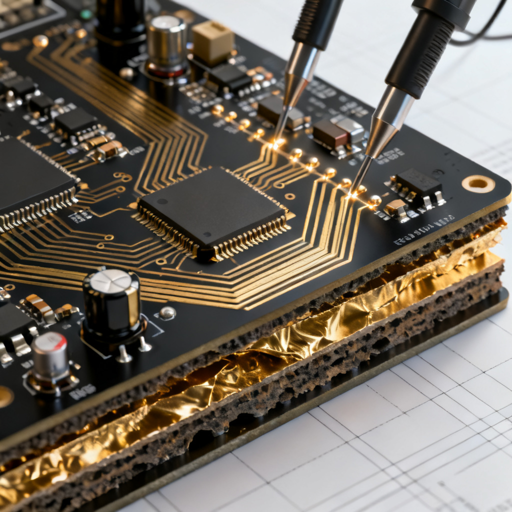
Consumer electronics represent the largest volume of PCB production, characterized by high-density, miniaturized designs that prioritize cost-efficiency and fast time-to-market. Common applications include smartphones, tablets, laptops, wearables, smart home devices, and gaming consoles.
Key PCB Types for Consumer Electronics
High-Density Interconnect (HDI) PCBs, flexible PCBs (FPCs), and rigid-flex PCBs are prevalent due to their ability to pack more components into smaller spaces.
Materials in Consumer PCBs
Standard FR-4 is widely used for its balance of cost and performance. For high-frequency applications like 5G smartphones, low-loss materials such as Rogers or Isola are employed.
Design Considerations for Consumer PCBs
Consumer PCBs often feature fine-line traces (down to 3 mils), multiple layers (up to 12+), and via-in-pad technology. Thermal management is critical due to heat from processors and batteries. Surface mount technology (SMT) dominates assembly.
Reliability and Testing in Consumer Electronics
While consumer devices undergo functional testing, they may have less stringent environmental testing compared to industrial or aerospace PCBs. However, drop testing and temperature cycling are common for wearables and mobile devices.
Examples of Consumer PCBs
A smartphone PCB integrates RF circuits, power management, memory, and sensors on a single board. Smart home devices like thermostats rely on low-power, IoT-enabled PCBs with wireless modules.
Automotive Electronics
The automotive industry has seen a surge in PCB usage due to electric vehicles (EVs), advanced driver-assistance systems (ADAS), and infotainment. Automotive PCBs must withstand harsh conditions: extreme temperatures (-40°C to +150°C), vibration, humidity, and exposure to chemicals.
Key PCB Types for Automotive
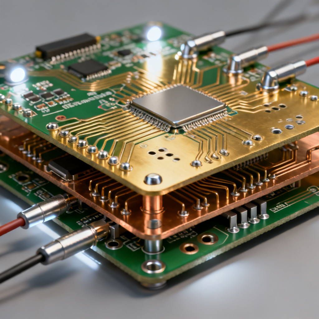
Multilayer rigid PCBs (up to 16 layers), flexible PCBs for tight spaces (e.g., dashboard connections), and heavy-copper PCBs for high-current applications (e.g., battery management systems).
Materials in Automotive PCBs
High-Tg (glass transition temperature) FR-4 is standard, but for under-hood applications, polyimide or ceramic-filled laminates are used. Materials must meet AEC-Q100/200 reliability standards.
Design Considerations for Automotive PCBs
Automotive PCBs require robust solder joints, wide trace widths for current capacity, and conformal coating for moisture protection. EMI shielding is critical for ADAS sensors.
Reliability and Testing in Automotive
Stringent testing includes thermal shock, vibration, and accelerated life testing. ISO 26262 (functional safety) compliance is mandatory for safety-critical systems like braking and steering.
Examples of Automotive PCBs
EV battery management systems (BMS) use thick copper PCBs (up to 4 oz) to handle high currents. ADAS camera modules rely on HDI PCBs for signal integrity in radar and lidar systems.
Medical Devices
Medical PCBs are designed for patient safety, precision, and reliability, often operating in life-critical environments. Applications include diagnostic imaging (MRI, CT scanners), patient monitoring, implantable devices, and laboratory equipment.
Key PCB Types for Medical Devices
Rigid, flexible, and rigid-flex PCBs are used. Implantable devices require ultra-thin, biocompatible flexible PCBs. High-layer-count boards are common in complex imaging systems.
Materials in Medical PCBs
For implantables, materials must be biocompatible (e.g., liquid crystal polymer or polyimide). Standard medical PCBs use high-reliability FR-4 or ceramic substrates for thermal stability.
Design Considerations for Medical PCBs
Creepage and clearance distances are critical for patient isolation. Redundant circuits and fail-safe designs are common. Signal integrity is paramount in high-resolution imaging.
Reliability and Testing in Medical Devices
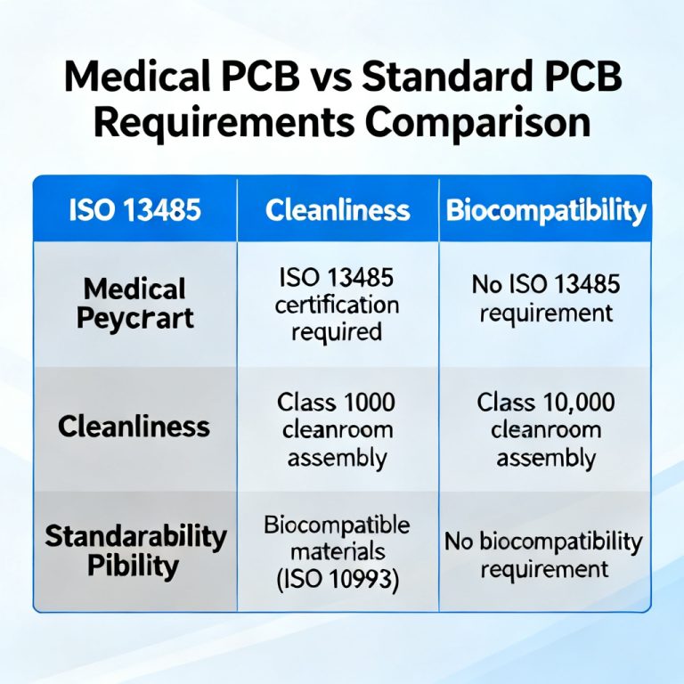
Medical PCBs must pass IPC Class 3 (high reliability) standards. Testing includes burn-in, accelerated aging, and EMC compliance per IEC 60601. Biocompatibility testing per ISO 10993 is required for implantables.
Examples of Medical PCBs
A pacemaker PCB is ultra-miniaturized with low-power circuitry. An MRI machine uses large, multi-layer PCBs with high-frequency materials for gradient coil control.
Industrial Equipment
Industrial PCBs are used in automation, robotics, power supplies, and control systems. They must operate reliably in factories, warehouses, and outdoor environments with dust, humidity, and temperature extremes.
Key PCB Types for Industrial Equipment
Single-sided and double-sided PCBs for simple controls, multilayer PCBs for complex PLCs, and heavy-copper PCBs (up to 20 oz) for motor drives and power converters.
Materials in Industrial PCBs
Standard FR-4 is common, but for high-temperature environments (e.g., near furnaces), polyimide or high-Tg materials are used. Conformal coating is standard for moisture and dust resistance.
Design Considerations for Industrial PCBs
Industrial PCBs prioritize robustness over miniaturization. Wide traces, large pads, and thick copper ensure current handling. Screw terminals and high-reliability connectors are typical.
Reliability and Testing in Industrial Equipment
IPC Class 2 (dedicated service) is typical, but Class 3 is used for critical systems. Testing includes thermal cycling, humidity, and vibration. Long product lifecycles (10+ years) require careful component selection.
Examples of Industrial PCBs
A robotic arm controller uses a multi-layer PCB with FPGA and power stages. A solar inverter employs heavy-copper PCBs for DC-to-AC conversion.
Telecommunications
Telecom infrastructure demands PCBs that support high-speed data transmission, low signal loss, and high thermal dissipation. Applications include base stations, routers, switches, fiber optic transceivers, and 5G antennas.
Key PCB Types for Telecommunications
High-frequency PCBs (e.g., Rogers, Taconic) for RF circuits, multi-layer backplanes (up to 30+ layers), and HDI PCBs for compact base station modules.
Materials in Telecom PCBs
Low-loss, low-dielectric-constant materials (e.g., PTFE, hydrocarbon ceramics) are essential for high-frequency signals. Copper-clad laminates with low roughness are used for minimal signal attenuation.
Design Considerations for Telecom PCBs
Controlled impedance (e.g., 50Ω or 100Ω differential) is critical. Via stubs must be minimized using back-drilling. Thermal management via heat sinks or copper coin inserts is common.
Reliability and Testing in Telecommunications
Telecom PCBs must meet Telcordia GR-468 or GR-1221 standards. Testing includes passive intermodulation (PIM) testing, thermal shock, and accelerated life testing.
Examples of Telecom PCBs
A 5G base station uses a multi-layer, high-frequency PCB for beamforming antennas. A fiber optic transceiver employs a rigid-flex PCB for compact integration.
Military and Defense
Military PCBs are designed for extreme reliability in harsh environments, including shock, vibration, temperature extremes, and electromagnetic interference (EMI). Applications include radar, electronic warfare, communication systems, and weapon guidance.
Key PCB Types for Military and Defense
Multilayer rigid PCBs (up to 40 layers) with high-density interconnects, flexible PCBs for ruggedized cables, and metal-core PCBs for thermal management.
Materials in Military PCBs
High-reliability materials like polyimide, cyanate ester, or PTFE are used. Conformal coating and hermetic sealing are common for moisture and chemical resistance.
Design Considerations for Military PCBs
Military PCBs follow MIL-PRF-31032 or MIL-STD-1553 standards. EMI shielding, ground planes, and filtering are critical. Redundant circuits and heavy copper (up to 10 oz) are used for high-current applications.
Reliability and Testing in Military and Defense
IPC Class 3 (high reliability) is mandatory. Testing includes thermal shock (MIL-STD-883), vibration (MIL-STD-202), and salt fog. Burn-in and X-ray inspection are routine.
Examples of Military PCBs
A radar system uses a multi-layer PCB with high-frequency materials for phased array antennas. A military communication radio employs a rigid-flex PCB for shock resistance.
Aerospace and Avionics
Aerospace PCBs are among the most demanding, requiring unparalleled reliability in extreme conditions: vacuum, radiation, temperature swings (-55°C to +125°C), and high vibration. Applications include satellite systems, aircraft avionics, flight control, and space exploration.
Key PCB Types for Aerospace
Multilayer rigid PCBs (up to 30 layers), rigid-flex PCBs for weight savings, and aluminum-backed PCBs for thermal management. HDI is used for compact satellite payloads.
Materials in Aerospace PCBs
Polyimide and cyanate ester are preferred for their thermal stability and outgassing resistance (low-outgassing per ASTM E595). For high-frequency applications, PTFE-based materials are used. Materials must be radiation-tolerant for space use.
Design Considerations for Aerospace PCBs
Aerospace PCBs prioritize reliability over cost. Wide margins are used for trace spacing and current capacity. Redundant power and ground planes are common. For space, tin whisker mitigation (e.g., using ENIG or immersion silver) is critical.
Reliability and Testing in Aerospace
Compliance with IPC Class 3 and AS9100 (aerospace quality) is required. Testing includes thermal vacuum cycling, vibration (MIL-STD-810), radiation testing, and burn-in. For space, NASA standards (e.g., NASA-STD-8739) apply.
Examples of Aerospace PCBs
A satellite communication PCB uses high-frequency materials for signal transmission. An aircraft flight control PCB features redundant layers and conformal coating for safety.
Selecting the Right PCB for Your Application
To choose the optimal PCB, consider these factors:
- Environmental Conditions: Temperature, humidity, vibration, and chemical exposure.
- Electrical Requirements: Voltage, current, frequency, and signal integrity.
- Mechanical Constraints: Size, shape, and weight.
- Regulatory Standards: IPC, ISO, MIL, or FDA compliance.
- Cost and Lead Time: Balance performance with budget and production timeline.
Partner with a PCB manufacturer that offers design for manufacturing (DFM) support, prototype services, and certifications for your target industry. A reliable supplier ensures your PCB meets all performance and reliability requirements.
Conclusion
PCBs are integral to modern technology, with applications ranging from everyday consumer electronics to life-saving medical devices and cutting-edge aerospace systems. Each industry imposes unique demands, driving innovation in materials, design, and manufacturing. By understanding these applications, you can make informed decisions that optimize performance, reliability, and cost. Whether you are developing a smartwatch or a satellite, the right PCB is the foundation of success.
Frequently Asked Questions (FAQ)
What is a PCB applications guide?
A PCB applications guide is a comprehensive resource that explains how printed circuit boards are used across different industries, from consumer electronics to aerospace.
How do I choose the right PCB for my application?
Choosing the right PCB involves evaluating environmental conditions, electrical requirements, mechanical constraints, regulatory standards, and cost. This PCB applications guide provides detailed criteria for each industry.
Why is PCB material selection important in aerospace?
In aerospace, PCB material selection is critical due to extreme temperatures, radiation, and vacuum. Materials like polyimide and PTFE are used for their thermal stability and low outgassing, as detailed in this PCB applications guide.
What are the key differences between consumer and military PCBs?
Consumer PCBs prioritize cost and miniaturization, while military PCBs focus on extreme reliability and durability under harsh conditions. This PCB applications guide highlights these contrasts.
Can the same PCB design be used for automotive and medical devices?
No, automotive and medical PCBs have different reliability standards and material requirements. This PCB applications guide explains the specific needs of each sector.
| Industry | Key PCB Type | Typical Layer Count | Common Materials | Reliability Standard |
|---|---|---|---|---|
| Consumer Electronics | HDI, Flexible | 4-12 | FR-4, Rogers | IPC Class 2 |
| Automotive | Multilayer Rigid, Heavy Copper | 4-16 | High-Tg FR-4, Polyimide | AEC-Q100/200 |
| Medical | Rigid-Flex, Flexible | 2-20 | Biocompatible Polymers, Ceramic | IPC Class 3 |
| Industrial | Single/Double Sided, Heavy Copper | 1-8 | FR-4, Polyimide | IPC Class 2/3 |
| Telecommunications | High-Frequency, Backplane | 10-30+ | PTFE, Hydrocarbon Ceramics | Telcordia GR-468 |
| Military & Defense | Multilayer, Metal-Core | 10-40 | Polyimide, Cyanate Ester | MIL-PRF-31032 |
| Aerospace | Rigid-Flex, Aluminum-Backed | 8-30 | Polyimide, PTFE | AS9100, IPC Class 3 |