LED PCB Application Aluminum Core COB High Power
This comprehensive guide explores LED PCB Application Aluminum Core COB High Power designs, providing engineers and procurement professionals with authoritative technical insights for reliable lighting solutions.
Aluminum Core PCBs – The Thermal Backbone for LED PCB Application
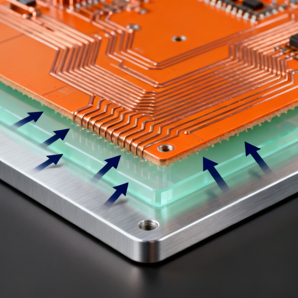
What Is an Aluminum Core PCB in LED PCB Application?
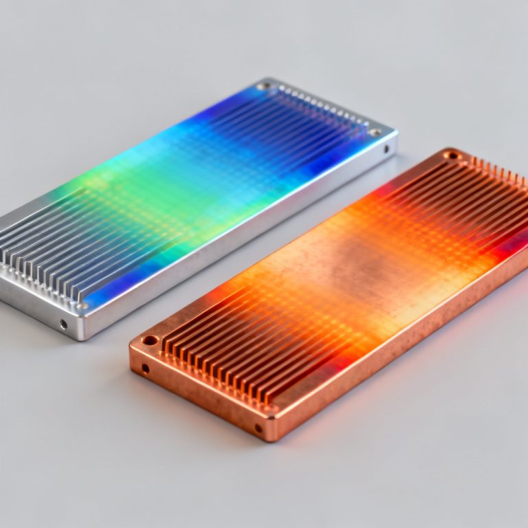
An aluminum core PCB (metal-core PCB or MCPCB) replaces standard FR4 with an aluminum alloy layer acting as a heat sink. The stack-up includes a copper circuit layer, a thermally conductive dielectric, and a thick aluminum base, reducing thermal resistance up to 10x compared to FR4. This makes it ideal for LED PCB application requiring efficient heat dissipation.
Thermal Management Advantages for LED PCB Application
Aluminum’s thermal conductivity (150–200 W/mK) far exceeds FR4’s 0.3 W/mK. For high-brightness LEDs generating 10–50 W/m², aluminum core prevents junction temperature spikes. Advanced dielectrics offer 1–3 W/mK while maintaining 2–5 kV isolation. Copper thickness of 2–4 oz handles 5–10 A currents without voltage drop in demanding LED PCB application.
Applications of Aluminum Core PCBs in LED PCB Application
Street Lighting: 100–200 W LED streetlights maintain <85°C junction temperature for 50,000+ hour lifetimes.
Automotive Headlights: High-beam and DRLs use compact, vibration-resistant MCPCBs.
Industrial High-Bay Lights: 200–500 W fixtures use multi-layer aluminum core PCBs with thermal vias.
UV LED Curing Systems: Aluminum core handles intense heat from 365–405 nm UV LEDs.
Design Considerations for LED PCB Application
Thermal Via Arrays: 0.3–0.5 mm vias filled with conductive epoxy improve heat transfer by 20–30%.
Dielectric Thickness: Keep 50–100 µm to balance thermal resistance and breakdown voltage.
Edge Clearance: Maintain 5–10 mm from PCB edges to aluminum core.
Solder Mask: Use high-Tg solder mask (>150°C) for reflow soldering.
Chip-on-Board (COB) PCBs – High-Density Light Engines for LED PCB Application
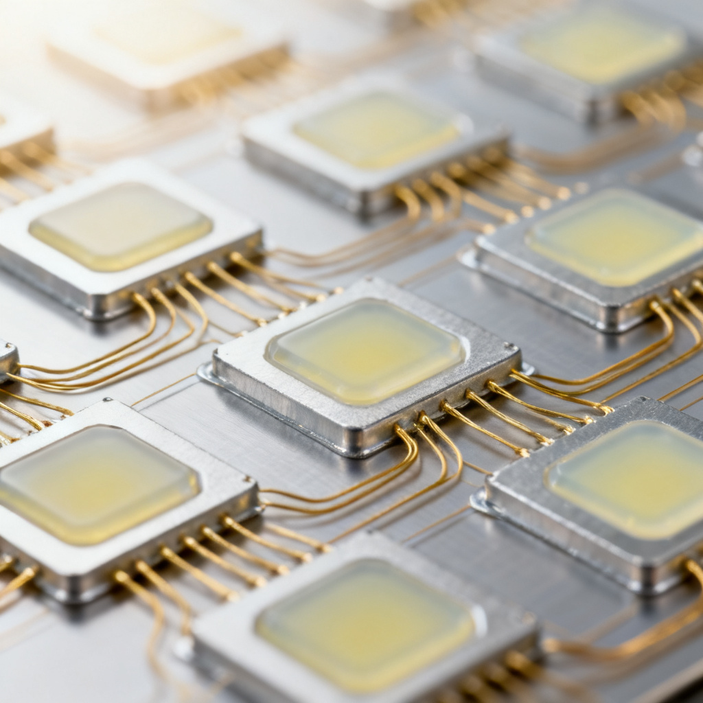
What Is a COB PCB in LED PCB Application?
Chip-on-Board technology mounts bare LED chips directly onto a substrate (aluminum core or ceramic) with phosphor-coated silicone encapsulation. This achieves >90% packing density, producing 500–5,000 lumens from a single source. COB PCBs are essential for LED PCB application in directional lighting.
Key Technical Specifications for LED PCB Application
Chip Count: 9–100+ chips in a 10×10 mm area.
CRI: Achieves >90 (up to 98 for premium) by blending blue chips with phosphors.
CCT: Available from 2700 K to 6500 K with ±50 K binning.
Voltage/Current: Forward voltage 30–40 V for 10-chip arrays; current 350 mA to 1.5 A.
Applications of COB PCBs in LED PCB Application
Architectural Lighting: Recessed downlights and track lights for uniform illumination.
Medical Lighting: Surgical lamps require CRI >95; COB arrays with 40–60 chips deliver this.
Horticultural LEDs: COB PCBs with red (660 nm) and blue (450 nm) chips for photosynthesis.
Retail Display Lighting: COB spotlights with precise 10–60° beam angles.
Manufacturing Challenges for LED PCB Application
Wire Bonding: Gold or aluminum wires (25–50 µm) connect chip pads to PCB pads; optimize for aluminum core to prevent cratering.
Phosphor Coating: Apply uniform 100–500 µm silicone-phosphor mixture; non-uniform coating causes color shift (∆u’v’ >0.005).
Solder Joint Reliability: Use SAC305 solder with controlled reflow profile (peak 245°C, ramp rate <2°C/s).
High Power LED PCBs – Pushing the Limits in LED PCB Application
Defining High Power in LED PCB Application
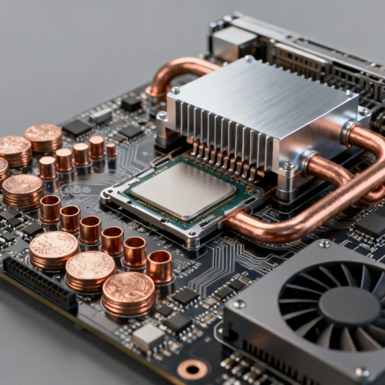
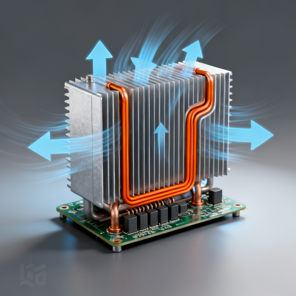
High power LED PCBs handle >1 W per LED (often 3–10 W) and total board power >50 W. Configurations include single-layer MCPCB for 1–3 W LEDs, multi-layer MCPCB with 4 oz copper and heat pipes, and hybrid designs combining FR4 signal layers with aluminum core power layers for smart lighting.
Thermal Solutions for LED PCB Application
Heat Sinks: Attach finned aluminum heat sinks (0.5–2°C/W) using TIMs like graphite pads.
Active Cooling: For >100 W boards, integrate fans or liquid cooling channels.
Thermal Simulation: Use Flotherm or Ansys Icepak; keep Tj <125°C for standard LEDs, <105°C for automotive-grade.
Current Handling and Routing for LED PCB Application
Trace Width: For 5 A, use 3–5 mm traces with 2 oz copper; for 10 A, use 8–12 mm traces.
Via Sizing: Use 0.5–1.0 mm vias with copper plating >25 µm; fill with solder or thermal epoxy.
Voltage Isolation: Maintain 2–3 mm creepage between high-voltage and low-voltage traces in AC-powered designs.
Applications of High Power PCBs in LED PCB Application
Outdoor Floodlights: 100–500 W fixtures use multi-layer MCPCBs with 3–5 LED arrays.
Automotive Matrix Lighting: Adaptive headlights require 50–100 individually addressable LEDs at 1–2 A each.
Industrial UV Curing: 400–800 W UV LED arrays use water-cooled aluminum core PCBs.
Stage Lighting: Moving head spotlights use high-power COB modules (200–600 W) with DMX control.
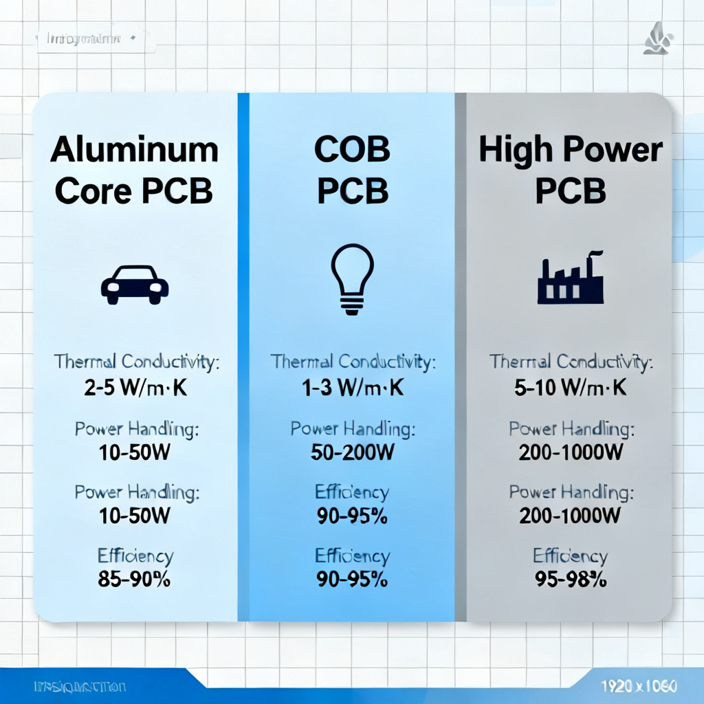
LED PCB Application Comparison Table: Aluminum Core vs COB vs High Power
| Feature | Aluminum Core PCB | COB PCB | High Power PCB |
|---|---|---|---|
| Heat Dissipation | Excellent (via aluminum base) | Excellent (integrated into substrate) | Requires external heat sink/cooling |
| Luminous Flux per Area | Moderate (single LED packages) | Very high (dense chip arrays) | High (multiple high-wattage LEDs) |
| Design Complexity | Low (single layer) | Medium (wire bonding, phosphor) | High (multi-layer, current management) |
| Cost per Lumen | Low to Medium | Medium to High | High |
| Typical Lifetime | 50,000–100,000 hours | 30,000–70,000 hours | 20,000–50,000 hours (with cooling) |
| Best For | General lighting, automotive | Directional, high-CRI lighting | Extreme brightness, industrial |
How to Select the Right LED PCB Application for Your Project
Step 1: Define Power and Thermal Requirements
<10 W total: Standard aluminum core PCB with 1 oz copper, 1.5 mm aluminum.
10–50 W per LED: Use high-power MCPCB with 2–4 oz copper and thermal vias.
>50 W total: Consider COB arrays on aluminum core with active cooling.
Step 2: Determine Optical Needs
Beam Angle: COB modules offer narrow beams (10–30°) for spotlights; discrete LEDs on MCPCBs provide wider angles (60–120°).
CRI/CCT: For retail or medical, choose COB with CRI >95 and CCT binning.
Step 3: Evaluate Environmental Factors
Humidity: Aluminum core PCBs with ENIG surface finish resist corrosion; COB modules require conformal coating.
Vibration: Automotive and marine applications need thick aluminum core (2–3 mm) and underfill for COB chips.
UV Exposure: Use ceramic-based COB substrates for UV LEDs; aluminum core degrades under prolonged UV.
Step 4: Consider Manufacturing and Cost
Prototyping: Aluminum core PCBs are cheapest for small volumes; COB requires specialized wire bonding equipment.
Mass Production: High-power PCBs with multi-layer MCPCBs have longer lead times (10–15 days vs. 5–7 days).
Testing: All LED PCBs should undergo thermal cycling (-40°C to +125°C, 500 cycles) and current stress tests (1.5× rated current for 100 hours).
Manufacturing Best Practices for LED PCB Application
Material Selection
Aluminum Alloy: Use 6061-T6 or 5052-H32 for balance of thermal conductivity and machinability.
Copper Foil: Electrodeposited copper with 2–4 oz thickness ensures low electrical resistance.
Dielectric: Choose between standard (1 W/mK) and high-performance (3 W/mK) dielectrics; the latter costs 30–50% more but extends LED life by 20%.
Fabrication Process
Drilling: Use carbide drills for aluminum core to prevent burr formation; maintain 0.1 mm tolerance.
Plating: Apply electroless copper (0.5–1.0 µm) followed by electrolytic copper (25–35 µm) for vias.
Solder Mask: Use LPI solder mask with matte finish to reduce light reflection in COB modules.
Quality Control
Thermal Resistance Testing: Measure RθJB using T3Ster; target <3°C/W for MCPCBs.
X-Ray Inspection: Check for voids in thermal vias and solder joints; acceptable void area <10%.
Optical Testing: For COB modules, measure luminous flux and color uniformity with integrating sphere and spectroradiometer.
Industry Terminology for LED PCB Application
MCPCB: Metal Core Printed Circuit Board, typically aluminum-based.
COB: Chip-on-Board, bare LED chips mounted directly on substrate.
CRI: Color Rendering Index, measures light accuracy.
CCT: Correlated Color Temperature, measured in Kelvin.
TIM: Thermal Interface Material, used between PCB and heat sink.
Tj: Junction Temperature, critical for LED lifespan.
RθJB: Thermal resistance from junction to board.
ENIG: Electroless Nickel Immersion Gold, surface finish for corrosion resistance.
FAQ: LED PCB Application – Aluminum Core, COB, High Power
What is the best LED PCB application for high brightness lighting?
How does aluminum core improve LED PCB application thermal performance?
What is the difference between COB and standard LED PCB application?
Can I use aluminum core PCB for high power LED PCB application?
What is the typical lifetime for different LED PCB application types?
Our Expertise in LED PCB Application
We specialize in custom aluminum core PCBs (0.8 mm to 3.2 mm thickness), COB PCB assembly with automated wire bonding and phosphor coating, and high power PCB thermal simulation with 48-hour prototyping. Our engineers review thermal, optical, and environmental requirements for every LED PCB application. Request a quote for your next project.
{ “@context”: “https://schema.org”, “@type”: “Article”, “headline”: “LED PCB Application Aluminum Core COB High Power”, “description”: “A comprehensive guide exploring LED PCB applications, focusing on aluminum core MCPCBs, Chip-on-Board (COB) technology, and high power thermal management solutions.”, “image”: “https://pcbtypes.com/wp-content/uploads/cob-led-pcb-application-chip-on-board.jpg”, “author”: { “@type”: “Organization”, “name”: “PCB Types”, “url”: “https://pcbtypes.com/” }, “publisher”: { “@type”: “Organization”, “name”: “PCB Types”, “logo”: { “@type”: “ImageObject”, “url”: “https://pcbtypes.com/logo.png” } }, “datePublished”: “2026-07-02”, “mainEntityOfPage”: “https://pcbtypes.com/led-pcb-application-aluminum-core-cob-high-power/” } { “@context”: “https://schema.org”, “@type”: “BreadcrumbList”, “description”: “Breadcrumb navigation for LED PCB Application guide”, “itemListElement”: [ { “@type”: “ListItem”, “position”: 1, “name”: “Home”, “item”: “https://pcbtypes.com/” }, { “@type”: “ListItem”, “position”: 2, “name”: “LED PCB Application”, “item”: “https://pcbtypes.com/category/led-pcb-application/” }, { “@type”: “ListItem”, “position”: 3, “name”: “LED PCB Application Aluminum Core COB High Power”, “item”: “https://pcbtypes.com/led-pcb-application-aluminum-core-cob-high-power/” } ] } { “@context”: “https://schema.org”, “@type”: “BreadcrumbList”, “description”: “Breadcrumb navigation for LED PCB Application guide”, “itemListElement”: [ { “@type”: “ListItem”, “position”: 1, “name”: “Home”, “item”: “https://pcbtypes.com/” }, { “@type”: “ListItem”, “position”: 2, “name”: “LED PCB Application”, “item”: “https://pcbtypes.com/category/led-pcb-application/” }, { “@type”: “ListItem”, “position”: 3, “name”: “LED PCB Application Aluminum Core COB High Power”, “item”: “https://pcbtypes.com/led-pcb-application-aluminum-core-cob-high-power/” } ] }