Medical PCB Guide ISO 13485 Cleanliness Implantable Requirements
Here is Medical PCB Guide ISO 13485 Cleanliness Implantable Requirements. In the rapidly evolving landscape of medical technology, the Medical PCB is the silent backbone of life-saving and life-enhancing devices. From diagnostic imaging systems and patient monitors to implantable pacemakers and wearable health trackers, the reliability of a Medical PCB is non-negotiable. A single failure can compromise patient safety, lead to costly recalls, or even result in loss of life. This guide provides a deep dive into the three most critical pillars of Medical PCB manufacturing: adherence to the ISO 13485 quality management standard, achieving the required cleanliness levels, and meeting the stringent implantable device requirements.
Part 1: The Foundation – ISO 13485 Quality Management System for Medical PCB
1.1 What is ISO 13485 and Why Does It Matter for Medical PCB?
ISO 13485 is an internationally recognized standard for Quality Management Systems (QMS) specifically designed for medical device manufacturers. It is not merely a checklist but a comprehensive framework that ensures consistent design, development, production, and delivery of medical devices that are safe for their intended purpose. For a Medical PCB manufacturer, ISO 13485 certification is the first and most critical trust signal.
1.2 Key Requirements of ISO 13485 for Medical PCB Fabrication
Design Control: ISO 13485 mandates rigorous design control processes. This means every Medical PCB design must undergo formal review, verification, and validation. For example, a Medical PCB for an infusion pump must have documented evidence that it meets the specified impedance, thermal, and signal integrity requirements before production begins. Any design change triggers a full re-review.
Document Control and Traceability: Every step of the Medical PCB manufacturing process must be documented and traceable. From the specific lot number of the copper-clad laminate to the soldering temperature profile and the final electrical test results, a complete history of each board must be available. This traceability is vital for root cause analysis in the event of a field failure.
Risk Management (ISO 14971 Integration): While ISO 13485 itself requires risk management, the most effective Medical PCB manufacturers integrate ISO 14971 (Application of Risk Management to Medical Devices) directly into their processes. This means that during the design and fabrication of a Medical PCB, potential hazards (e.g., short circuits, corrosion, material fatigue) are identified, analyzed, and mitigated. For instance, a risk analysis might dictate the use of an ENIG (Electroless Nickel Immersion Gold) surface finish over HASL (Hot Air Solder Leveling) to prevent whisker growth in a high-reliability application.
Supplier Control: The manufacturer must have a robust system for evaluating and monitoring all suppliers of raw materials (laminates, solder mask, surface finish chemicals). This ensures that the quality of incoming materials is consistently high and that any changes in supplier materials are managed through a formal change control process.
Corrective and Preventive Actions (CAPA): A formal CAPA system is mandatory. When a non-conformity is identified (e.g., an out-of-spec impedance measurement), the manufacturer must investigate the root cause, implement a corrective action to fix the immediate issue, and define a preventive action to ensure it never happens again. This continuous improvement cycle is the heart of ISO 13485.
1.3 Differences Between ISO 13485 and Standard ISO 9001 for Medical PCB
While ISO 9001 is a general QMS standard, ISO 13485 is much more prescriptive for the medical device industry. Key differences include:
- Regulatory Focus: ISO 13485 places a much stronger emphasis on regulatory compliance, including the need to comply with local regulations like the FDA’s Quality System Regulation (QSR) in the U.S. and the Medical Device Regulation (MDR) in the EU.
- Design Control Rigor: ISO 13485 requires a more formal and documented design control process than ISO 9001.
- Traceability: The traceability requirements under ISO 13485 are far more stringent, especially for implantable devices.
- Validation of Processes: ISO 13485 mandates the validation of specific production processes where the resulting output cannot be verified by subsequent monitoring or measurement (e.g., the lamination process for multilayer PCBs).
Part 2: Cleanliness Requirements for Medical PCB
2.1 Why Cleanliness is Paramount for Medical PCB
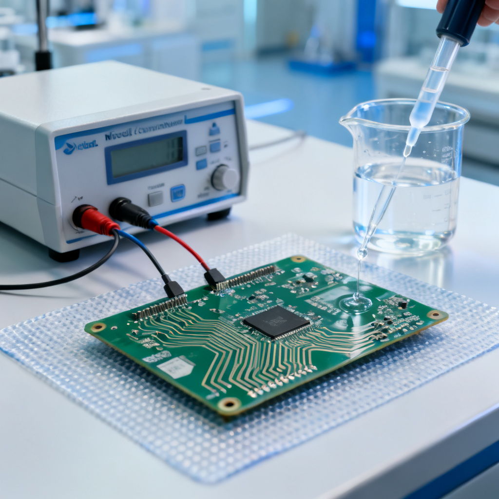
Contamination on a Medical PCB is a primary cause of failure. Ionic residues (from flux, etching, or plating processes) can create conductive paths, leading to electrochemical migration, dendritic growth, and ultimately, short circuits. Non-ionic residues (like dust, oils, or solder balls) can cause intermittent failures, corrosion, or physical interference with components. In a medical context, this is unacceptable.
2.2 The Standard: IPC-6012 and IPC-A-600 for Medical PCB
The most widely referenced cleanliness standard for Medical PCB is IPC-6012 (Qualification and Performance Specification for Rigid Printed Boards) and the associated visual acceptance criteria in IPC-A-600 (Acceptability of Printed Boards). For medical devices, the highest class, Class 3, is typically required. Class 3 is defined as “High Reliability Electronic Products” where continued performance or performance-on-demand is critical, and equipment downtime cannot be tolerated. This includes life support systems and implantable devices.
2.3 Measuring Cleanliness: Key Tests and Limits for Medical PCB
- Ionic Contamination Testing (e.g., IPC-TM-650, Method 2.3.25): This is the most common quantitative test. A Medical PCB is placed in a heated solution of isopropyl alcohol and deionized water, which dissolves any ionic residues. The solution’s conductivity is then measured to determine the total ionic contamination, typically expressed in micrograms of sodium chloride equivalent per square inch (µg NaCl/in²). For medical Class 3 PCBs, the industry standard is typically < 1.56 µg NaCl/in², though some high-reliability applications demand even lower limits, such as < 0.5 µg NaCl/in².
- Surface Insulation Resistance (SIR) Testing (e.g., IPC-TM-650, Method 2.6.3.3): This test assesses the resistance between two conductive patterns on the Medical PCB surface after exposure to a controlled temperature, humidity, and bias voltage. A high SIR value (e.g., > 100 MΩ) indicates a clean surface with low risk of leakage currents.
- Visual Inspection (under magnification): IPC-A-600 defines acceptable levels of surface imperfections like pitting, scratches, and exposed copper. For Medical PCB, the surface must be free of any visible residues, including flux, solder balls, and foreign particles.
- Outgassing Testing (for space and implantable): For hermetic or implantable devices, outgassing testing (e.g., ASTM E595) is critical. The Medical PCB is heated in a vacuum, and the amount of volatile condensable material (VCM) and collected volatile condensable material (CVCM) is measured. Limits are typically < 1.0% TML (Total Mass Loss) and < 0.1% CVCM.
2.4 Achieving and Maintaining Cleanliness in Medical PCB Manufacturing
- Process Control: The choice of solder mask, surface finish, and flux (if used) directly impacts cleanliness. No-clean fluxes are often avoided for Class 3 Medical PCB in favor of water-soluble fluxes that require thorough washing.
- Cleaning Processes: Aqueous cleaning systems using deionized water and saponifiers are standard. Ultrasonic cleaning is sometimes used for complex geometries. The cleaning process must be validated to consistently achieve the required cleanliness level.
- Cleanroom Environment: For high-reliability Medical PCB, final assembly and inspection are often performed in a controlled cleanroom environment (e.g., ISO Class 7 or 8) to minimize airborne particulate contamination.
- Packaging: After cleaning and final inspection, Medical PCB must be immediately sealed in anti-static, moisture-barrier bags to prevent recontamination.
Part 3: Implantable PCB Requirements for Medical PCB
3.1 The Unique Challenges of Implantable Medical PCB
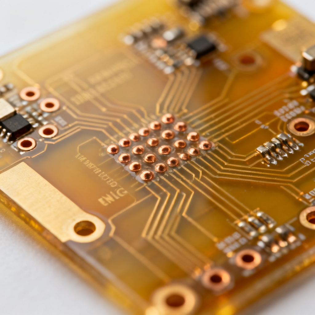
Implantable medical devices (e.g., pacemakers, neurostimulators, cochlear implants) operate inside the human body for years or even decades. This environment is harsh: constant temperature (37°C), high humidity (100% RH), exposure to corrosive bodily fluids (salts, proteins, enzymes), and mechanical stress (movement, flexing). The Medical PCB must be biocompatible, ultra-reliable, and miniaturized.
3.2 Key Material and Design Requirements for Implantable Medical PCB
- Biocompatible Materials: The Medical PCB substrate and all surface finishes must be biocompatible per ISO 10993 (Biological evaluation of medical devices). This typically means using high-purity polyimide or liquid crystal polymer (LCP) as the base material, which are inert and do not leach harmful substances. The surface finish is almost exclusively ENIG (Electroless Nickel Immersion Gold) or ENEPIG (Electroless Nickel Electroless Palladium Immersion Gold) because of their excellent corrosion resistance and biocompatibility. HASL and OSP are unacceptable.
- Ultra-High Reliability: Implantable Medical PCB are designed with extremely wide safety margins. Trace widths, spacing, and annular rings are often 50-100% larger than the minimum required by IPC-6012 Class 3. This ensures tolerance to manufacturing variations and long-term degradation.
- Miniaturization and High Density: Implantable devices are extremely small. This requires advanced Medical PCB technologies like HDI (High-Density Interconnect) with microvias (laser-drilled vias < 150 µm), fine lines and spaces (< 75 µm), and sequential lamination.
- Flex and Rigid-Flex Designs: Many implantable devices use flexible or rigid-flex Medical PCB to conform to the curved shape of the body, reduce mechanical stress on solder joints, and allow for articulation (e.g., in a cochlear implant lead). The flex material must be a biocompatible polyimide.
- Hermeticity and Encapsulation: While the Medical PCB itself may not be hermetically sealed, the final device is. The Medical PCB must be designed to withstand the encapsulation process (e.g., potting with medical-grade silicone or epoxy) and the thermal stresses of any subsequent welding or sealing processes. The Medical PCB surface must be free of any sharp edges or burrs that could puncture the encapsulation.
3.3 Specialized Manufacturing Processes for Implantable Medical PCB
- Controlled Impedance: For high-frequency signals (e.g., in a cochlear implant or deep brain stimulator), controlled impedance is critical. The manufacturer must provide impedance coupons and test reports for every panel.
- 100% Electrical Testing: Every implantable Medical PCB must undergo 100% electrical testing, including flying probe testing for opens and shorts, and possibly automated optical inspection (AOI) and X-ray inspection for internal layers and hidden solder joints.
- X-Ray Inspection: For multilayer and HDI boards, X-ray inspection is used to verify the alignment and integrity of buried vias and internal layers.
- Lot Traceability: A complete and unbroken chain of traceability from the raw material lot to the finished, tested board is mandatory. Each individual Medical PCB is often laser-marked with a unique serial number that encodes its entire manufacturing history.
3.4 Regulatory and Certification Requirements for Implantable Medical PCB
- ISO 13485: The manufacturer must be certified to ISO 13485.
- FDA Registration: For the U.S. market, the Medical PCB manufacturer must be registered with the FDA and their facility must comply with the FDA’s Quality System Regulation (21 CFR Part 820). The Medical PCB is typically considered a component of a Class III medical device (e.g., an implantable pacemaker).
- ISO 10993: The Medical PCB materials must be tested and shown to be biocompatible per ISO 10993. This includes tests for cytotoxicity, sensitization, and irritation.
- UL Certification: While not always mandatory for implantable components, UL certification (e.g., UL 796 for PCB base materials) is often required to ensure flame retardancy and electrical safety.
- Country-Specific Regulations: For global markets, compliance with local regulations is necessary, such as the EU MDR (Medical Device Regulation) and Japan’s PMD Act.
Comparison: Medical PCB vs Standard PCB Requirements
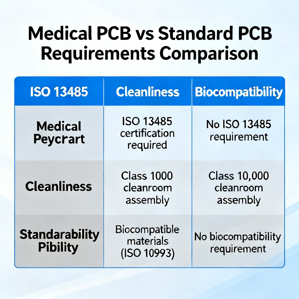
| Specification | Standard Commercial PCB | Medical PCB (Class 3 / Implantable) |
|---|---|---|
| Quality Management System | ISO 9001 (optional) | ISO 13485 (mandatory) |
| Cleanliness (Ionic) | < 10 µg NaCl/in² (typical) | < 1.56 µg NaCl/in² (Class 3) |
| Surface Finish | HASL, OSP, ENIG | ENIG or ENEPIG (biocompatible) |
| Material Biocompatibility | Not required | ISO 10993 (mandatory for implantable) |
| Electrical Testing | Sampling or 100% | 100% (flying probe + X-ray) |
| Traceability | Lot-level | Unit-level (laser marking) |
Frequently Asked Questions (FAQ) About Medical PCB
What is the most important certification for a Medical PCB manufacturer?
The most important certification for a Medical PCB manufacturer is ISO 13485. This standard ensures the manufacturer has a robust quality management system specifically designed for medical device components, including rigorous design control, traceability, and risk management processes.
How clean does a Medical PCB need to be for implantable devices?
For implantable devices, a Medical PCB must meet Class 3 cleanliness standards per IPC-6012. The typical limit for ionic contamination is < 1.56 µg NaCl/in², though high-reliability applications may require < 0.5 µg NaCl/in². This is achieved through validated aqueous cleaning processes and verified by ionic contamination testing.
What surface finish is recommended for implantable Medical PCBs?
For implantable Medical PCB, the recommended surface finishes are ENIG (Electroless Nickel Immersion Gold) or ENEPIG (Electroless Nickel Electroless Palladium Immersion Gold). These finishes provide excellent corrosion resistance, biocompatibility per ISO 10993, and are suitable for fine-pitch components. HASL and OSP are not acceptable due to biocompatibility concerns.
What is the difference between ISO 13485 and ISO 9001 for Medical PCBs?
ISO 13485 is specifically designed for medical device manufacturing, while ISO 9001 is a general quality management standard. For Medical PCB, ISO 13485 requires more stringent design control, traceability (often to the individual board level), risk management integration (ISO 14971), and regulatory compliance with FDA and EU MDR. ISO 9001 does not address these medical-specific requirements.
Why is traceability critical for Medical PCBs in implantable devices?
Traceability is critical for implantable Medical PCB because it enables complete root cause analysis in the event of a device failure. Each Medical PCB is often laser-marked with a unique serial number that links to its entire manufacturing history, including material lots, process parameters, and test results. This allows manufacturers to quickly identify and recall affected devices if a defect is found.