Metal Core Materials Aluminum Copper Insulation Layer
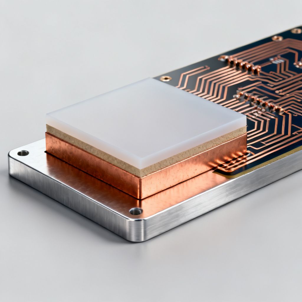
In high-power electronics, thermal management is critical, and Metal Core Materials Aluminum Copper Insulation Layer define the performance of Metal Core PCBs (MCPCBs). These boards, also known as Insulated Metal Substrate (IMS) boards, are essential for LED lighting, automotive power systems, and industrial motor drives. This guide covers every aspect of metal core materials, dielectric insulation, and copper circuit layers to help engineers and procurement professionals make informed decisions.
- Metal Core: Aluminum vs. Copper
- Dielectric Insulation Layer
- Copper Circuit Layer
- Material Selection Criteria
- Manufacturing Considerations
- Common Pitfalls
- FAQ
Metal Core: Aluminum vs. Copper for Thermal Management
The metal core is the foundation of an MCPCB, providing mechanical support and acting as a heat sink. The choice between aluminum and copper for Metal Core Materials – Aluminum, Copper, Insulation Layer depends on thermal requirements, weight, and cost.
Aluminum Core – Industry Standard for Metal Core Materials
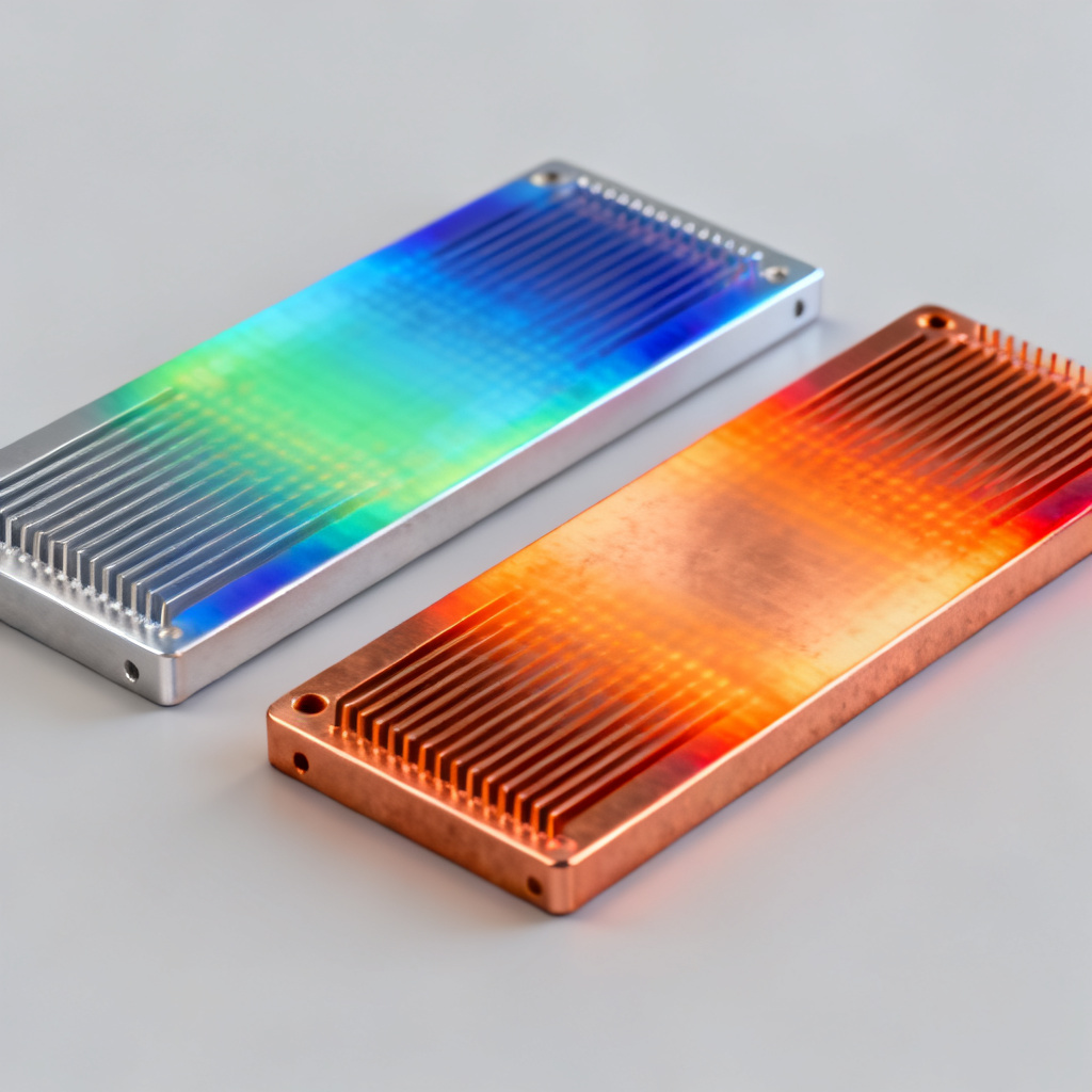
Aluminum is the most widely used metal core material due to its balance of thermal conductivity, lightweight properties, and cost-effectiveness. Standard aluminum cores (e.g., 1050, 6061 alloys) have a thermal conductivity of approximately 200–230 W/mK for the metal base, while the entire stack-up ranges from 1.0 to 3.0 W/mK. Aluminum is lighter than copper, reducing weight by 30–50% in many designs, and it offers excellent machinability for punching, drilling, and routing. However, aluminum has a higher Coefficient of Thermal Expansion (CTE) (~23 ppm/°C) compared to copper, which can cause stress on solder joints during thermal cycling. For general LED lighting and consumer electronics, aluminum is the cost-effective choice, but for extreme thermal demands, copper is preferred.
Copper Core – High-Performance Metal Core Material
Copper cores are reserved for the most demanding thermal environments, offering thermal conductivity of ~390–401 W/mK (pure copper), nearly double that of aluminum. Copper-based boards achieve thermal resistance values as low as 0.5–1.0 °C/W, compared to 1.5–3.0 °C/W for aluminum. Copper’s CTE (~17 ppm/°C) is closer to silicon and ceramic substrates, reducing thermal stress in high-temperature cycling applications. However, copper is three times denser than aluminum, making it unsuitable for weight-sensitive designs, and it increases PCB cost by 2–5 times. Specialized metal cores like steel (for mechanical strength or magnetic shielding) and hybrid cores (copper-clad aluminum) offer alternative solutions.
Dielectric Insulation Layer – Thermal Bridge in Metal Core PCBs
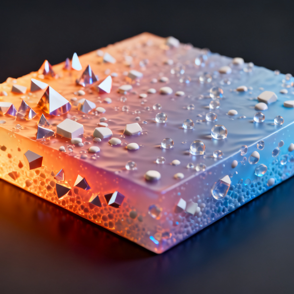
The dielectric layer is the most critical component in Metal Core Materials – Aluminum, Copper, Insulation Layer, electrically isolating the copper circuit while allowing heat to pass through. Its thermal resistance (Rth) is the primary bottleneck in the entire thermal path. The dielectric is a composite material made of a polymer matrix (epoxy, polyimide, or PTFE) and thermally conductive fillers such as aluminum oxide (Al₂O₃), boron nitride (BN), or aluminum nitride (AlN). Filler content can reach 70–90% by volume, and glass fiber reinforcement is added for mechanical stability.
Key Parameters of Dielectric Insulation
Thermal conductivity (k) ranges from 0.5 W/mK (standard FR4-like materials) to 8.0 W/mK (high-performance ceramics). Dielectric strength must withstand operating voltages, typically 3–15 kV/mm. Dielectric constant (Dk) is important for high-frequency applications; standard materials have Dk ~3.5–5.0 at 1 MHz, while PTFE-based materials achieve Dk as low as 2.2. Thickness ranges from 25 µm to 200 µm, with thinner layers reducing thermal resistance but increasing risk of electrical breakdown. Glass transition temperature (Tg) should exceed the maximum operating temperature, with standard materials at 130–150°C and high-Tg materials at 180–200°C.
Types of Dielectric Materials for Metal Core PCBs
Standard epoxy-based dielectrics (e.g., Bergquist MP-06503) offer thermal conductivity of 1.0–2.0 W/mK at low cost, suitable for consumer LEDs. High-performance epoxy (e.g., Ventec VT-4B3) provides 2.0–4.0 W/mK for automotive and industrial applications. Ceramic-filled polyimide (e.g., Panasonic PGS) achieves up to 8.0 W/mK with high Tg (260°C) for high-power RF and aerospace. PTFE-based materials (e.g., Rogers 3000 series) have low Dk and low loss for high-frequency applications, though thermal conductivity is moderate (0.5–1.5 W/mK), often combined with thermal via arrays. Thermal resistance (Rth) is calculated as Rth = Thickness / (Thermal Conductivity × Area). To minimize Rth, designers can reduce dielectric thickness, increase filler loading, or use thermal via arrays.
Copper Circuit Layer – Conductivity and Reliability
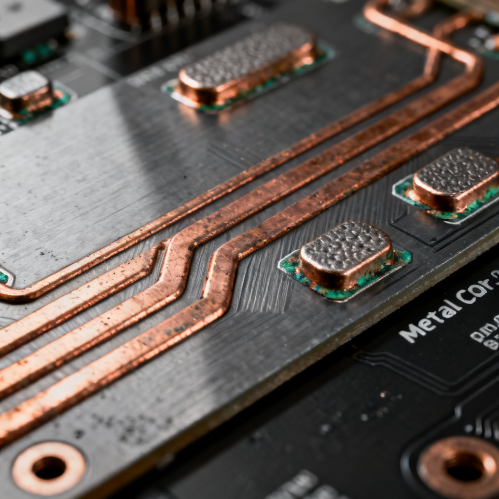
The copper circuit layer carries electrical signals and current. In Metal Core Materials – Aluminum, Copper, Insulation Layer, this layer is typically thicker than in standard PCBs to handle higher currents and improve heat spreading. Standard copper thickness is 1 oz (35 µm) or 2 oz (70 µm) for low-power LEDs, while heavy copper (3 oz to 10 oz, i.e., 105 µm to 350 µm) is used for high-current power electronics. Ultra-thick copper up to 20 oz (700 µm) is used for bus bars and IGBT modules. Thicker copper reduces electrical resistance and improves heat spreading from components to the dielectric.
Surface Finish and Trace Design
Common surface finishes for MCPCBs include HASL (low cost, but not for fine-pitch components), ENIG (excellent flatness and corrosion resistance), OSP (low cost but limited shelf life), and immersion silver (good for high-frequency but tarnishes in sulfur-rich environments). For thermal management, use wide traces to reduce electrical resistance and act as heat spreaders. Large copper pads under high-power components should be directly connected to the dielectric layer without solder mask. Via-in-pad with thermally conductive epoxy can improve heat transfer to the metal core, though it adds cost.
Material Selection Criteria for Metal Core PCBs
Choosing the right combination of metal core, dielectric, and copper thickness requires balancing thermal, electrical, mechanical, and cost requirements. Below is a practical decision matrix for Metal Core Materials – Aluminum, Copper, Insulation Layer.
| Application | Metal Core | Dielectric Type | Copper Thickness | Key Consideration |
|---|---|---|---|---|
| General LED Lighting (e.g., bulbs, strips) | Aluminum (1050) | Standard Epoxy (1.0–2.0 W/mK) | 1 oz (35 µm) | Cost-effective, sufficient thermal performance |
| High-Power LED (e.g., streetlights, stadiums) | Aluminum (6061) or Copper | High-Performance Epoxy (2.0–4.0 W/mK) | 2–4 oz (70–140 µm) | Need low Rth, good heat spreading |
| Automotive Power (e.g., headlights, motor controllers) | Copper (C1100) | Ceramic-Filled Polyimide (3.0–6.0 W/mK) | 4–10 oz (140–350 µm) | High reliability, vibration resistance, high Tg |
| High-Frequency RF (e.g., 5G antennas, radar) | Copper | PTFE-Based (low Dk, low loss) | 1–2 oz (35–70 µm) | Low signal loss, controlled impedance |
| Industrial Motor Drives (IGBT modules) | Copper | High-Tg Epoxy (3.0–5.0 W/mK) | 10–20 oz (350–700 µm) | Extreme current, thermal cycling durability |
Manufacturing Considerations for Metal Core PCBs
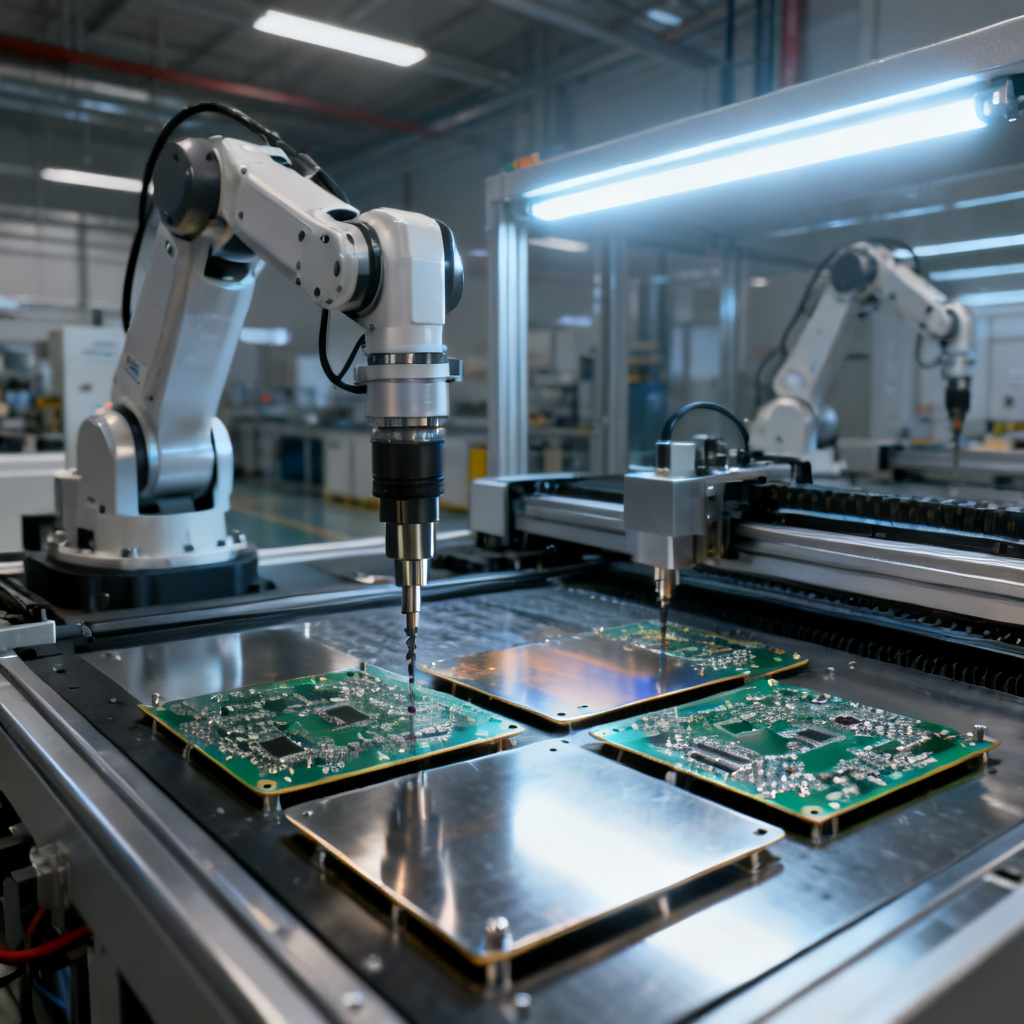
Manufacturing Metal Core Materials – Aluminum, Copper, Insulation Layer requires specialized processes. Metal core preparation involves cutting, deburring, and cleaning; for aluminum, chemical etching or anodizing improves adhesion of the dielectric. Dielectric lamination uses prepreg under high temperature (160–200°C) and pressure (200–400 psi) to ensure void-free bonding. Circuit patterning uses standard photolithography and etching, but thick metal cores require special etching solutions and longer processing times. Drilling and routing are harder than standard FR4; carbide drills with higher feed rates and lower speeds are used, and laser drilling may be needed for small vias in thick copper cores.
Quality Control Tests
Thermal resistance measurement (ASTM D5470) ensures dielectric Rth meets specifications. Dielectric strength tests apply high voltage (e.g., 1500 VAC) between the circuit layer and metal core. Thermal cycling from -40°C to +150°C (e.g., 1000 cycles) checks for delamination or cracking. Peel strength tests measure copper foil adhesion to the dielectric (minimum 1.0 N/mm per IPC-6012).
Common Pitfalls in Metal Core Material Selection
Avoid these common mistakes when working with Metal Core Materials – Aluminum, Copper, Insulation Layer. First, overlooking thermal resistance of the dielectric: the dielectric is the bottleneck, so always specify Rth of the entire stack-up, not just the metal. Second, using too thin a dielectric: while thinner reduces thermal resistance, it can lead to electrical breakdown; verify dielectric strength against operating voltage. Third, ignoring CTE mismatch: for high-temperature cycling, copper core with ceramic-filled dielectric reduces stress on solder joints. Fourth, inadequate copper thickness: insufficient thickness leads to excessive resistive heating. Fifth, poor Thermal Interface Material (TIM) selection: the MCPCB is only as good as its connection to the heatsink; use high-quality TIM with low thermal resistance.
FAQ: Metal Core Materials – Aluminum, Copper, Insulation Layer
What are Metal Core Materials – Aluminum, Copper, Insulation Layer used for?
These materials are used in Metal Core PCBs (MCPCBs) for applications requiring efficient heat dissipation, such as LED lighting, automotive power systems, and industrial motor drives. The combination of aluminum or copper core with a dielectric insulation layer and copper circuit layer ensures thermal management and electrical reliability.
How do I choose between aluminum and copper for my Metal Core PCB?
Choose aluminum for cost-effective, lightweight designs with moderate thermal needs, such as general LED lighting. Choose copper for high-power applications requiring superior heat dissipation and lower CTE, such as automotive power modules or industrial IGBT systems. The decision matrix in this guide provides detailed guidance.
What is the role of the dielectric insulation layer in Metal Core Materials?
The dielectric layer electrically isolates the copper circuit from the metal core while allowing heat to pass through. Its thermal resistance (Rth) is critical for overall thermal performance. Materials like ceramic-filled polyimide or PTFE-based dielectrics are used depending on thermal and frequency requirements.
What copper thickness is recommended for high-current Metal Core PCBs?
For high-current designs, heavy copper of 3 oz to 10 oz (105 µm to 350 µm) is recommended, and ultra-thick copper up to 20 oz (700 µm) for extreme applications like IGBT modules. Thicker copper reduces electrical resistance and improves heat spreading.
What are common mistakes in Metal Core PCB design?
Common pitfalls include overlooking dielectric thermal resistance, using too thin a dielectric, ignoring CTE mismatch, inadequate copper thickness, and poor TIM selection. Each can degrade thermal performance and reliability.