Through Hole Assembly Wave Soldering Hand Soldering
Through hole assembly remains a cornerstone of reliable PCB production, with wave soldering and hand soldering as the two primary methods for creating robust electrical and mechanical connections. This comprehensive guide covers both processes in full technical detail.
Wave Soldering Process for Through‑Hole Assembly
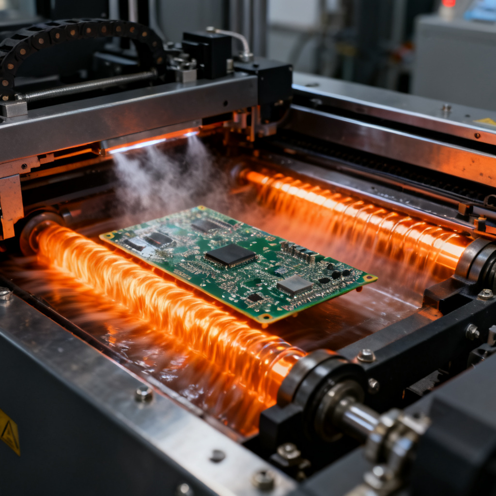
Wave soldering is an automated bulk soldering process designed for high‑volume through‑hole assembly, where the PCB passes over a molten solder wave to form consistent joints.
Step‑by‑Step Wave Soldering Workflow
The wave soldering process follows a precise sequence: flux application to remove oxides, preheating to activate the flux and reduce thermal shock, contact with the molten solder wave at 250–260°C, and controlled cooling to solidify joints. Each step is critical for achieving reliable through‑hole assembly results.
Key Process Parameters for Wave Soldering
Optimal wave soldering parameters include solder temperature of 250–260°C for lead‑free alloys, conveyor speed of 1.0–1.8 m/min, wave height of 3–5 mm above the PCB bottom, and preheat temperature of 90–110°C. These settings ensure proper hole fill and joint quality in through‑hole assembly.
Common Wave Soldering Defects and Solutions
| Defect | Cause | Solution |
|---|---|---|
| Solder Bridges | Excess solder between adjacent pads/leads | Reduce wave height; increase conveyor speed; improve pad spacing |
| Insufficient Solder / Voids | Poor wetting; inadequate flux activity | Increase preheat; adjust flux type; ensure proper hole‑to‑lead ratio |
| Cold Joints | Insufficient temperature | Raise solder temperature; check wave contact |
| Flux Residue | Excessive or unactivated flux | Use no‑clean flux; improve preheat; clean if necessary |
Design for Wave Soldering (DFW)
Design rules for wave soldering include component orientation aligned with the wave direction, hole‑to‑lead ratio of 1.15:1 to 1.25:1, pad size at least 0.5 mm larger than the hole diameter, and thermal relief pads for connections to large copper planes. Proper DFW ensures defect‑free through‑hole assembly.
Hand Soldering Techniques for Through‑Hole Assembly
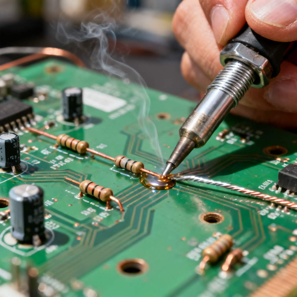
Hand soldering is essential for prototyping, rework, and low‑volume through‑hole assembly, offering flexibility for non‑standard components and mixed‑technology boards.
When to Use Hand Soldering
Hand soldering is ideal for small batches (1–100 boards), repairs, components with unusual pin pitches, and adding through‑hole parts to SMT boards. It provides precise control for critical through‑hole assembly applications.
Hand Soldering Process Steps
The hand soldering process involves cleaning pads and leads, inserting the component, heating the pad and lead simultaneously at 315–370°C, applying solder until it flows evenly, and inspecting for a shiny concave joint. Proper technique ensures high‑quality through‑hole assembly.
Essential Tools and Materials
Key tools for hand soldering include a temperature‑controlled iron (30–60 W), rosin‑core solder wire (Sn63Pb37 or SAC305), additional flux for difficult joints, and desoldering tools like wick or vacuum pump. These are standard for professional through‑hole assembly work.
Best Practices for Hand Soldering
Use the lowest effective tip temperature (315–350°C for lead‑free), limit dwell time to 2–4 seconds, solder components from lowest to tallest profile, and apply extra flux for large ground planes. These practices ensure reliable through‑hole assembly joints.
Common Hand Soldering Defects and Fixes
| Defect | Cause | Solution |
|---|---|---|
| Cold Joint | Insufficient heat; movement during cooling | Re‑heat the joint fully; allow it to cool without disturbance |
| Excess Solder / Balling | Too much solder; poor flux | Use less solder; improve flux activity |
| Lifted Pad | Excessive heat or mechanical stress | Reduce iron temperature; use a lower‑wattage iron; support the pad |
| Bridging | Solder connecting adjacent pads | Use solder wick to remove excess; improve iron tip placement |
Comparing Wave Soldering vs. Hand Soldering for Through‑Hole Assembly
Both methods serve distinct roles in through‑hole assembly. Wave soldering offers high throughput and consistency for mass production, while hand soldering provides flexibility and precision for prototypes and repairs. The table below highlights key differences.
| Parameter | Wave Soldering | Hand Soldering |
|---|---|---|
| Volume | High (1000s/day) | Low (1–100/day) |
| Cost per Joint | Very low | High (labor‑intensive) |
| Consistency | Excellent (automated) | Operator‑dependent |
| Flexibility | Low (requires tooling) | High (any component) |
| Best for | Bulk production, mixed‑tech | Prototypes, rework, repairs |
Selecting the Right Flux for Through‑Hole Assembly
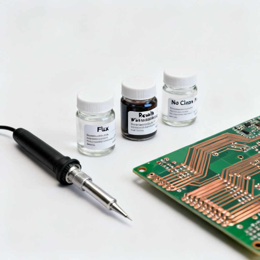
Flux is critical for both wave and hand soldering in through‑hole assembly. Rosin‑based (RMA) flux is suitable for general use with optional cleaning, water‑soluble (OA) flux provides high activity but requires thorough cleaning, and no‑clean flux leaves minimal residue—ideal for wave soldering to eliminate cleaning steps.
Quality Control and Inspection for Through‑Hole Assembly
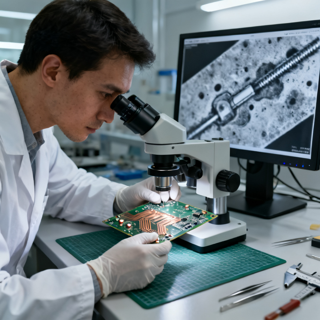
Quality control methods include visual inspection for shiny concave joints, X‑ray inspection for hidden joints, pull testing for mechanical strength (>5 N), cross‑sectioning for failure analysis, and adherence to IPC‑A‑610 standards for Class 1, 2, or 3 requirements. These ensure reliability in through‑hole assembly.
Frequently Asked Questions about Through‑Hole Assembly
Can wave soldering be used for double‑sided PCBs?
Yes, but only the bottom side is soldered in through‑hole assembly. Components on the top side must be glued or held by leads.
What is the ideal hole‑to‑lead ratio for wave soldering?
The ideal ratio for through‑hole assembly is 1.15:1 to 1.25:1, meaning the hole diameter is 0.15–0.25 mm larger than the lead diameter.
How do I avoid solder bridges in hand soldering?
Use a fine tip, reduce solder feed, and ensure proper pad spacing (>0.5 mm) during through‑hole assembly.
Is lead‑free solder mandatory?
For RoHS‑compliant products, yes. Leaded solder is still allowed for non‑consumer, military, or medical through‑hole assembly applications.
Can I hand solder a PCB designed for wave soldering?
Yes, but expect slower throughput and potential difficulty with heavy ground planes in through‑hole assembly.
Industry Terminology for Through‑Hole Assembly
Plated‑Through Hole (PTH): A hole in the PCB with a conductive coating that allows electrical connection between layers and component leads. Wetting: The ability of molten solder to spread and adhere to a metal surface. Thermal Relief: A pad design that reduces heat sinking to large copper planes during soldering. Capillary Action: The force that draws molten solder into a PTH during wave soldering. Understanding these terms improves through‑hole assembly expertise.