PCB Quality & Reliability: HALT, Thermal Cycling, Lifetime Testing Guide
Whether you are designing for aerospace, automotive, or medical devices, mastering PCB Quality Reliability HALT Thermal Cycling Lifetime testing workflows is non-negotiable for B2B buyers.
The Foundation: Why PCB Quality & Reliability Matters More Than Ever
PCB Quality & Reliability is not a single test; it is a system of processes, materials, and validations. A single PCB failure in the field can cost 10x to 100x more than the board itself. In automotive or medical applications, the cost includes recalls, lawsuits, and brand damage. Reliability testing is your insurance policy.
The Reliability Triangle
Three factors define PCB Quality & Reliability: design rules (trace width, spacing, via placement, stack-up), material selection (Tg, CTE, dielectric constant), and manufacturing process control (lamination cycles, etching quality, solder mask adhesion).
Standards You Must Know
- IPC-6012: Qualification and Performance Specification for Rigid PCBs.
- IPC-9701: Performance Test Methods for Surface Mount Solder Attachments.
- JEDEC JESD22: Environmental and reliability tests for semiconductor packages.
HALT (Highly Accelerated Lifetime Testing) for PCB Quality
What Is HALT?
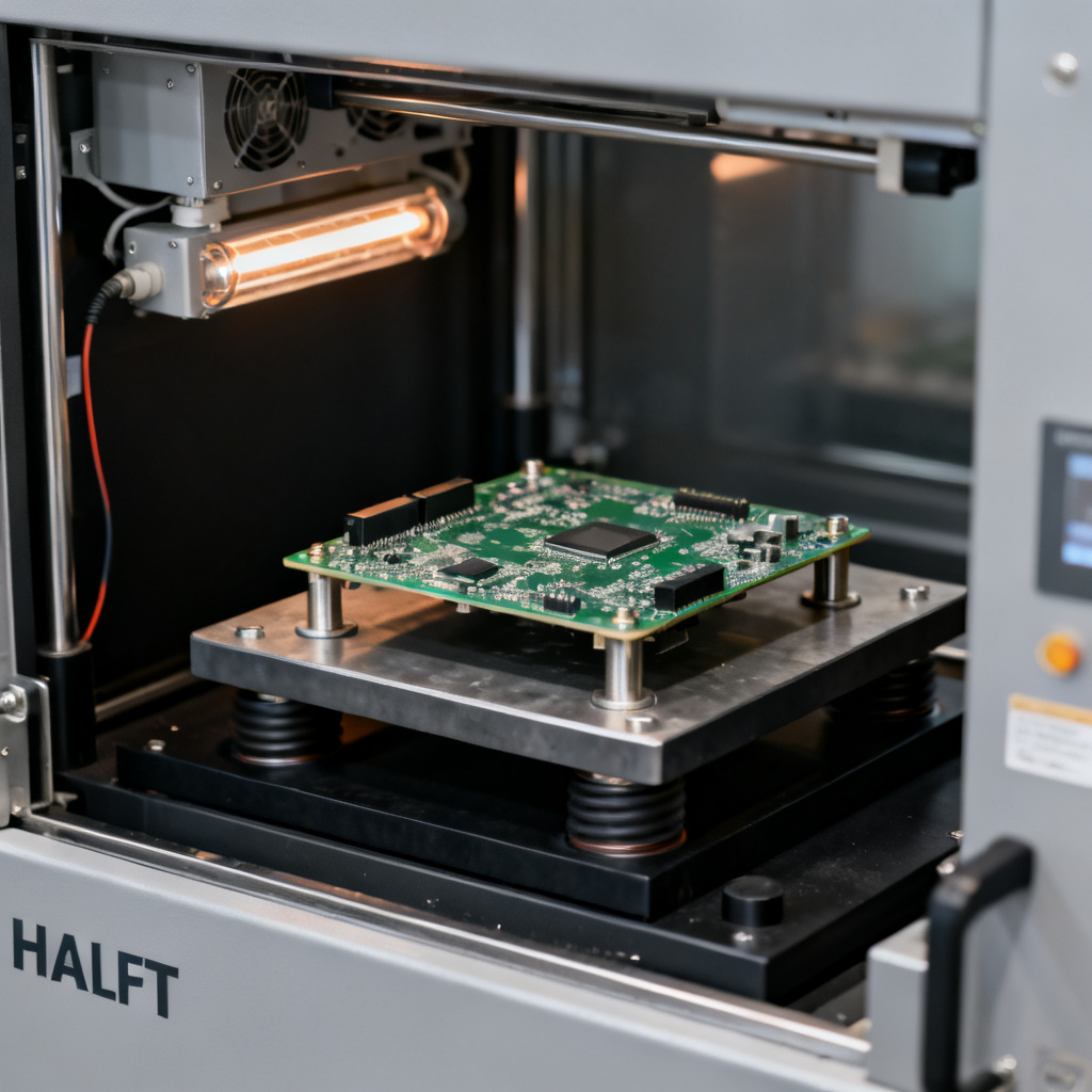
HALT is a destructive, step-stress test designed to find fundamental weaknesses in a PCB assembly. Unlike standard pass/fail tests, HALT pushes the product beyond its design limits until it breaks. The goal is not to simulate a lifetime of use but to expose latent defects in minutes.
How HALT Works (The Process)
- Cold Step Stress: Start at -40°C. Decrease temperature in steps until functional failure occurs.
- Hot Step Stress: Increase temperature from +85°C up to +150°C or until the board fails.
- Rapid Thermal Transitions: Cycle between hot and cold at rates of 40-60°C per minute to induce thermal shock.
- Vibration Step Stress: Apply random vibration from 5g to 50g RMS across a wide frequency range (20-2000 Hz).
- Combined Environment: Simultaneous thermal cycling and vibration—the most aggressive test.
What HALT Reveals
HALT reveals solder joint cracks (the most common failure mode), via barrel cracks (weak plating inside vias fails under thermal expansion), component delamination (poorly bonded laminates or solder mask lift off), and design margin weaknesses (trace routing that is too close to board edges).
When to Use HALT
- New Product Introduction (NPI): Validate first prototypes.
- Design Change Validation: After a material or layout change.
- Supplier Qualification: Compare different PCB fabricators.
HALT vs. HASS
HALT is destructive and used on a few samples to find the operating limit and destruct limit. HASS is non-destructive (ideally) and used on 100% of production units to screen out manufacturing defects. HASS is based on the margins found in HALT (typically 80% of the operating limit).
Thermal Cycling for PCB Quality & Reliability
What Is Thermal Cycling?
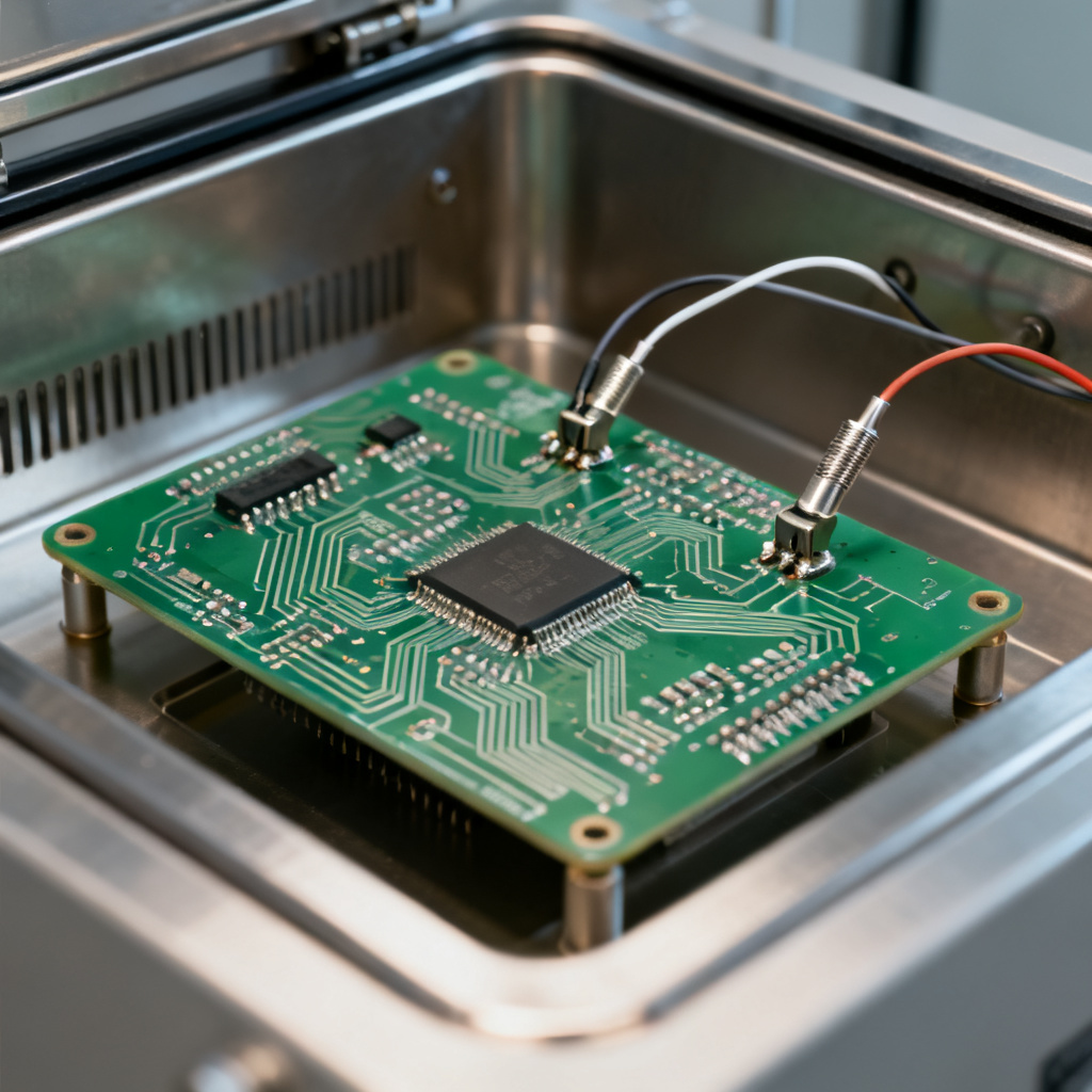
Thermal cycling (temperature cycling) is a controlled, non-destructive test that simulates thermal stresses a PCB will experience over its operational life. It is the gold standard for lifetime prediction because it directly stresses the weakest points: solder joints, plated through-holes (PTHs), and material interfaces.
Key Parameters
| Parameter | Typical Range |
|---|---|
| Temperature Range | -40°C to +125°C (automotive), -55°C to +150°C (aerospace) |
| Dwell Time | 10-30 minutes |
| Ramp Rate | 10-15°C per minute |
| Number of Cycles | 500 (consumer) to 2000+ (military) |
Failure Mechanisms Under Thermal Cycling
CTE mismatch (FR-4 expands differently than copper), solder joint fatigue (lead-free SAC305 is more brittle), copper plating fatigue (micro-cracks in PTH barrels), and dielectric breakdown (laminate micro-cracks leading to CAF growth) are common failures.
How to Interpret Thermal Cycling Results
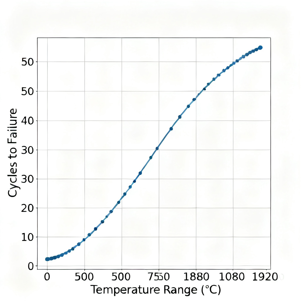
The industry standard is Weibull analysis. You test a sample of boards (e.g., 30 boards) and record the number of cycles to failure. The Weibull plot gives you characteristic life (η) and shape parameter (β). Example: A board with a characteristic life of 1500 cycles at -40°C to +125°C and expected 100 thermal cycles in its lifetime has a safety margin of 15x.
Thermal Cycling vs. Thermal Shock
Thermal cycling uses slow ramp rates (10-15°C/min) to test long-term fatigue. Thermal shock uses instantaneous transfer to test material adhesion and immediate cracking. Use thermal cycling for lifetime prediction; use thermal shock for solder joint integrity.
Lifetime Prediction & PCB Quality & Reliability Modeling
What Is Lifetime Prediction?
Lifetime prediction uses data from thermal cycling, HALT, and field data to estimate how long a PCB will function before failure. It is not a guarantee but a statistically valid estimate.
The Coffin-Manson Model
The most widely used model for solder joint fatigue is the Coffin-Manson relationship: Nf = C · (ΔT)⁻ⁿ. For SAC305 solder, n ≈ 2.0-2.5. A wider temperature range dramatically reduces lifetime.
Accelerated Life Testing (ALT)
ALT applies the Coffin-Manson model. You test at a higher temperature range and use the model to extrapolate to normal use conditions. Example: If a board fails at 500 cycles under accelerated conditions (ΔT = 200°C) and your use condition is ΔT = 60°C, the acceleration factor is approximately 11.1, predicting 5,550 cycles under use conditions.
The Role of Materials in PCB Quality & Reliability
- High Tg Materials: Higher Tg (170°C+) reduces CTE mismatch and improves thermal cycling lifetime by 2-3x.
- Copper Foil Type: Rolled annealed (RA) copper handles thermal cycling better than electrodeposited (ED) copper.
- Solder Mask: Liquid photoimageable (LPI) solder mask is more flexible and resists cracking.
Lifetime vs. Warranty
B10 life (time at which 10% of the population fails) is used for warranty calculations. Mean Time Between Failures (MTBF) is used for repairable systems. Design life is the target (e.g., 10 years for automotive, 20 years for aerospace).
Practical Integration: How to Use These Tests Together
The Reliability Workflow
- Design Phase: Use IPC-2221B rules for trace width, spacing, and via sizing. Select materials with Tg > 20°C above maximum operating temperature.
- Prototype Phase: Run HALT on 3-5 samples to find design weaknesses. Fix any failures.
- Qualification Phase: Run Thermal Cycling on 30-50 samples for 1000 cycles minimum. Perform Weibull analysis. Set lifetime target.
- Production Phase: Implement HASS (if high volume) or 100% visual inspection + AOI for low volume.
- Field Monitoring: Track returns and correlate with test data to refine models.
Common Mistakes to Avoid
- Skipping HALT: Thermal cycling alone will not find design margin weaknesses.
- Using wrong ramp rates: Too fast a ramp rate can cause thermal shock failures not representative of real use.
- Ignoring dwell time: Short dwell times may not fully stress the board; use 10-15 minutes minimum.
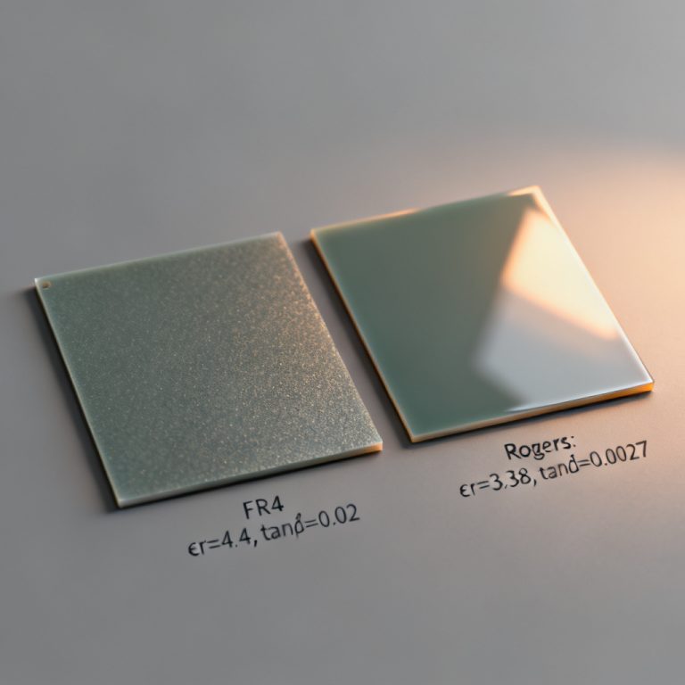
- Assuming all materials are equal: FR-4 from different suppliers has different CTE and Tg; always specify the IPC slash sheet.
Cost vs. Reliability Trade-off
| Application Level | Cycles | Materials | Testing |
|---|---|---|---|
| Standard Consumer | 100-500 | Standard FR-4, 1 oz copper | No HALT |
| Industrial | 500-1000 | High Tg FR-4, 2 oz copper | HALT on prototypes |
| Automotive/Aerospace | 1000-2000+ | Polyimide or PTFE, rolled copper | Full HALT + thermal cycling + Weibull |
Case Studies & Real-World Data
Case Study: Automotive ECU PCB
An 8-layer, 1.6mm thick, standard FR-4 board failed HALT at 120°C due to via barrel cracking. Fix: Changed to high Tg FR-4 (Tg 170°C) and increased via plating thickness from 20µm to 30µm. Thermal cycling result improved from 600 cycles to 1,800 cycles (3x improvement).
Case Study: Aerospace Power Supply
A 6-layer, 2 oz copper, polyimide board passed HALT to 150°C and 40g vibration. Thermal cycling result: characteristic life of 2,500 cycles at -55°C to +150°C. Lifetime prediction: 20+ years in a satellite (20 thermal cycles per year).
Industry Data
- Lead-free solder (SAC305) vs. Leaded (SnPb): Leaded solder has 2-5x longer thermal cycling life.
- Via Aspect Ratio: For a 1.6mm board, a 0.3mm via (aspect ratio 5.3:1) has 50% longer life than a 0.2mm via (aspect ratio 8:1).
- Copper Thickness: 2 oz copper vias have 30% longer thermal cycling life than 1 oz.
Frequently Asked Questions About PCB Quality & Reliability
Can I skip thermal cycling if I do HALT?
No. HALT finds design weaknesses; thermal cycling validates lifetime. Both are essential for comprehensive PCB Quality & Reliability.
How many samples do I need for a reliable lifetime prediction?
Minimum 30 boards for a Weibull analysis. Fewer samples give wide confidence intervals.
What is the most common failure mode in thermal cycling?
Via barrel cracking in PTHs, followed by solder joint fatigue at BGA corners.
Does a higher Tg always mean better reliability?
Not always. High Tg materials often have higher CTE (z-axis expansion), which can stress vias more. You must balance Tg with CTE.
How do I interpret a HALT test that shows no failure?
It means your design has a large margin. You can reduce the margin for cost savings, or keep it for high-reliability applications.
What is the difference between IPC-6012 Class 2 and Class 3?
Class 2 is standard reliability (consumer, industrial). Class 3 is high reliability (medical, aerospace) requiring tighter tolerances, 100% electrical testing, and additional thermal cycling.
Can I use thermal cycling data to predict field life?
Yes, if you know the field temperature profile. Use the Coffin-Manson model with an acceleration factor based on ΔT.
Conclusion: Your PCB Quality & Reliability Roadmap
By establishing a robust roadmap that prioritizes PCB Quality Reliability HALT Thermal Cycling Lifetime validation, you ensure your electronics survive decades of real-world abuse.