PCB Parameters, Specifications & Testing Methods: The Definitive Guide
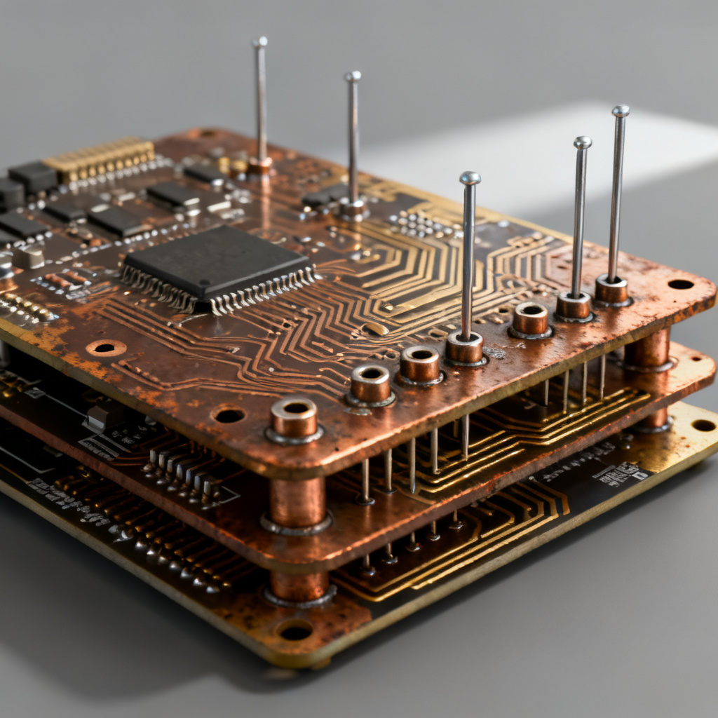
Understanding PCB Parameters Specifications Testing Methods is the foundation for reliable printed circuit board design and manufacturing. This guide consolidates expert knowledge from top industry sources to help you specify, verify, and trust every board you produce
Core PCB Parameters & Specifications
PCB Parameters, Specifications & Testing Methods begin with physical, electrical, and material definitions. These specifications govern signal integrity, mechanical durability, and overall performance.
Physical Dimensions & Mechanical Specifications
| PCB Parameter | Typical Value / Specification | Testing Method |
|---|---|---|
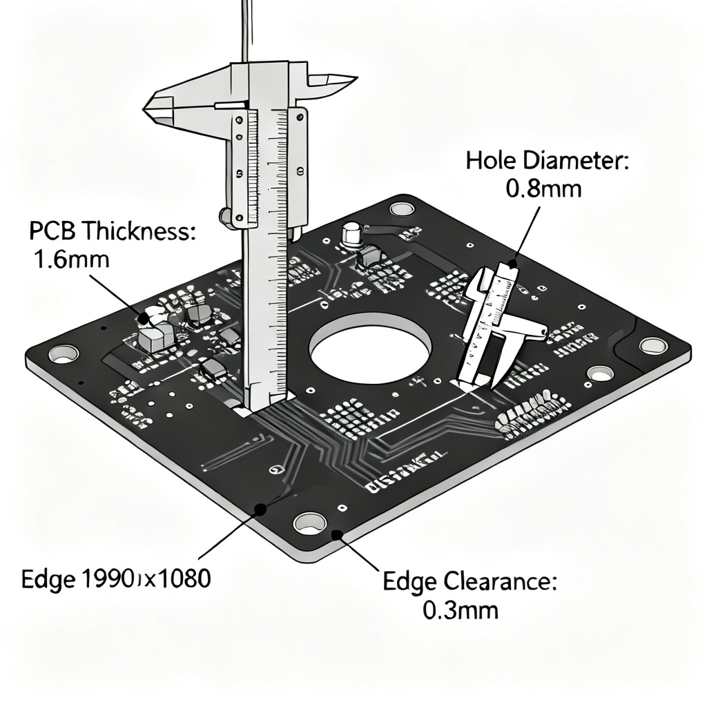
| Board Thickness | 0.8mm, 1.0mm, 1.6mm, 2.4mm (±10%) | Microsectioning, Caliper measurement |
| Copper Weight (Finished) | 0.5 oz, 1 oz, 2 oz, 4 oz | Cross-section analysis, weight measurement |
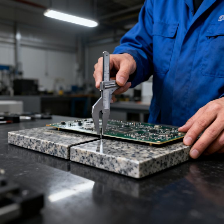
| Warpage / Bow | ≤0.75% (IPC-6012 Class 2), ≤0.5% for SMT | Flatness gauge, surface plate test |
| Minimum Hole Size | 0.2mm (standard), 0.1mm (HDI microvia) | Drill bit measurement, X-ray |
| Aspect Ratio | ≤10:1 (standard), up to 16:1 (advanced) | Calculated from thickness & hole diameter |
| Edge Clearance | 0.3mm – 0.5mm | Visual inspection, AOI |
Material Specifications
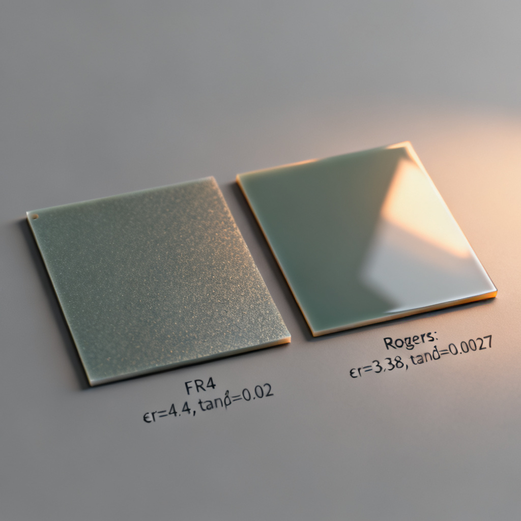
Material selection directly impacts PCB Parameters, Specifications & Testing Methods. Key material properties include Tg, Td, CTE, Dk, and Df.
- Tg (Glass Transition Temperature): Standard FR-4: 130–140°C; High-Tg: 170–180°C.
- Td (Decomposition Temperature): ≥350°C for high reliability.
- CTE (Coefficient of Thermal Expansion): Low Z-axis CTE prevents via cracking.
- Dk (Dielectric Constant) & Df (Dissipation Factor): FR-4 Dk ~4.5 at 1 GHz; Rogers 4350B Dk ~3.48.
- Solder Mask: LPI, thickness 0.5–1.0 mil, free of pinholes.
- Surface Finish: HASL, ENIG, OSP, Immersion Silver/Tin, Hard Gold.
Electrical Specifications
Controlled impedance is a critical PCB parameter. Typical targets: 50Ω single-ended, 100Ω differential, tolerance ±10% (±5% for critical designs). Current carrying capacity follows IPC-2152. Dielectric withstanding voltage tested at 500V or 1000V DC for 60 seconds. Insulation resistance ≥100 MΩ (often ≥1 GΩ).
Design & Manufacturing Tolerances
| PCB Parameter | Standard Tolerance | Advanced Tolerance |
|---|---|---|
| Trace Width/Spacing | ±20% | ±10% (min 2/2 mil) |
| Annular Ring | 0.05mm (Class 2) | 0.1mm (Class 3) |
| Layer Registration | ±0.075mm | ±0.05mm |
| Solder Mask Registration | ±0.1mm | ±0.05mm |
PCB Testing Methods for Quality Verification
Effective PCB testing methods confirm that every specification is met. These methods are categorized into electrical, mechanical, environmental, and specialized tests.
Electrical Testing

PCB testing methods for electrical integrity include:
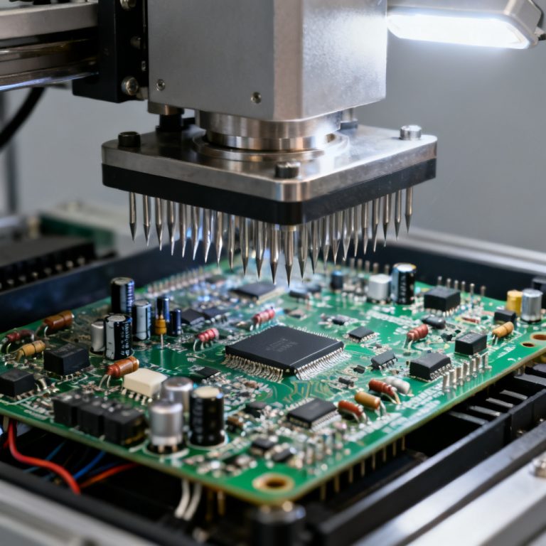
- Flying Probe Testing: Non-fixture, automated opens/shorts test. Ideal for prototypes.
- Fixture (Bed-of-Nails) Testing: High-speed, high-volume production test.
- Automated Optical Inspection (AOI): Visual defect detection using CAD comparison.
- X-Ray Inspection: Hidden solder joints (BGA, QFN), internal layer defects.
- Time Domain Reflectometry (TDR): Gold standard for controlled impedance verification.
Mechanical & Physical Testing
- Solderability Testing: Dip and look (IPC-J-STD-003) or wetting balance.
- Peel Strength Test: Copper foil adhesion to laminate (IPC-4101).
- Solder Mask Adhesion Test: Cross-hatch tape test (ASTM D3359).
- Thermal Stress Test: Solder float at 288°C for 10 seconds (IPC-TM-650 2.6.8).
- Microsectioning: Destructive cross-section analysis for copper thickness, plating, annular ring, registration.
Environmental & Reliability Testing
Reliability testing methods ensure long-term performance:
- Thermal Cycling: -40°C to +125°C, 100–1000 cycles.
- Thermal Shock: Rapid temperature change (15 sec transfer).
- Humidity Testing: 85°C/85% RH for 168–1000 hours.
- Vibration Testing: Sinusoidal or random profiles.
- Salt Spray Testing: 5% NaCl fog, 24–96 hours.
- HAST (Highly Accelerated Stress Test): 130°C/85% RH/pressure.
Specialized Testing for High Reliability
- Ionic Contamination (ROSE Test): Measures ionic residues (IPC-TM-650 2.3.25).
- CAF Testing: Conductive Anodic Filament growth detection (IPC-TM-650 2.6.25).
- SIR Testing: Surface Insulation Resistance under bias/humidity (IPC-TM-650 2.6.3.3).
- UL Flammability (UL 94): V-0, V-1, V-2, HB ratings.
- Bond Strength Test: Wire pull/shear for ENIG/hard gold surfaces.
Industry Standards & Compliance
All PCB Parameters, Specifications & Testing Methods adhere to international standards:
- IPC-6011 / IPC-6012: Generic and rigid board performance specifications.
- IPC-A-600: Acceptability of printed boards (visual criteria).
- IPC-2221: Generic design standard.
- IPC-4101: Base material specification.
- UL 94 / UL 796: Flammability and safety standards.
- ISO 9001: Quality management system.
- RoHS / REACH: Environmental compliance for export.
How to Specify Your PCB – A Practical Checklist
When ordering, provide these PCB parameters to your manufacturer:
- Board Type: Rigid, flexible, rigid-flex, HDI, high-frequency, aluminum-backed.
- Number of Layers: 2, 4, 6, 8, 10+.
- Dimensions: Length, width, thickness (with tolerance).
- Material: FR-4, High-Tg FR-4, Rogers, etc. Specify Tg, Dk, Df if critical.
- Copper Thickness: Outer and inner layers (in oz).
- Minimum Trace/Space: e.g., 4/4 mil, 3/3 mil.
- Minimum Hole Size: e.g., 0.3mm, 0.2mm.
- Surface Finish: HASL, ENIG, OSP, Immersion Silver, etc.
- Solder Mask & Silkscreen: Color and type.
- Impedance Control: Target impedance and tolerance.
- Testing Requirements: Flying probe, fixture, AOI, X-ray, microsection, etc.
- Certification Requirements: IPC-6012 class 2 or class 3, UL 94 V-0, RoHS, REACH.
- Quantity & Lead Time.