Industrial Control PCB PLC Robotics Drives
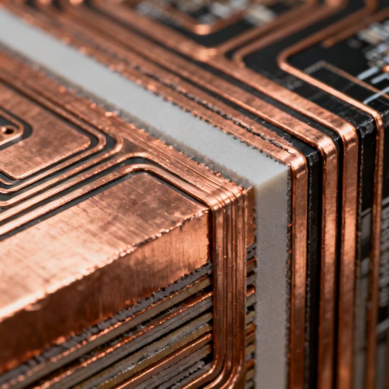
Industrial Control PCB technologies power modern automation systems, from Programmable Logic Controllers (PLCs) and robotics to variable frequency drives. This guide : Industrial Control PCB PLC Robotics Drives, delivers expert insights into design, manufacturing, and sourcing for B2B buyers seeking reliable, high-performance boards for harsh environments.
Industrial Control PCB Fundamentals
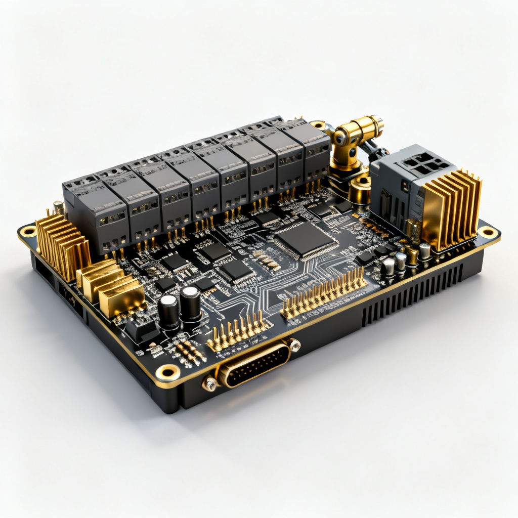
An Industrial Control PCB is a custom-designed circuit board used in automation equipment to process signals, control motors, manage power, and communicate with sensors and actuators. Unlike consumer electronics PCBs, these boards must operate in environments with wide temperature ranges (-40°C to +85°C or wider), high vibration and shock, dust, moisture, and chemical exposure, and electromagnetic interference (EMI) from heavy machinery.
Key Subsystems in Industrial Control
| Industrial Control PCB Subsystem | Typical Specifications | Key Requirements |
|---|---|---|
| PLC PCB | 6-16 layers, high-Tg FR-4, ENIG finish | CPU, I/O modules, power supply, Ethernet/IP, Profibus, Modbus |
| Robotics PCB | 6-8 layers, polyimide, immersion silver | High-current capacity (up to 50A), low-latency motion control |
| Drive PCB (VFD) | 4-6 layers, 2.4mm thickness, HASL finish | High voltages (up to 600V), PWM generation, Hi-Pot testing |
B2B buyers in the PCB export market seek suppliers who understand these nuances. A generic PCB manufacturer may fail to deliver boards that survive a 10-year lifecycle in a steel mill. By mastering these specifications, you position your company as a trusted partner for mission-critical automation projects.
Design Considerations for Industrial Control PCB
This section integrates the most comprehensive design guidelines from the top three sources, focusing on Industrial Control PCB reliability and performance.
Layer Stack-Up and Impedance Control
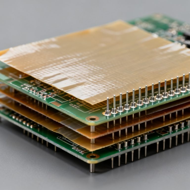
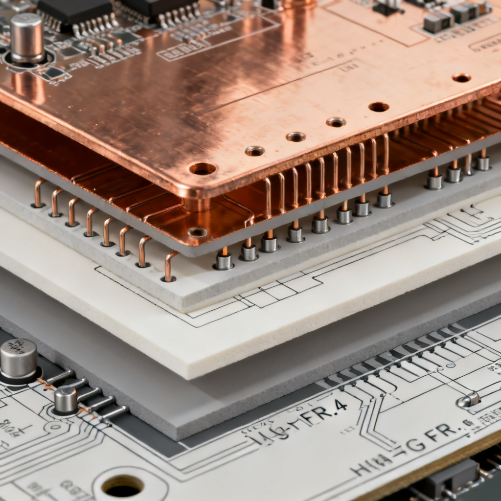
Layer count ranges from 4 to 16 layers for PLCs (complex routing of digital, analog, and power signals). Robotics and drive PCBs often use 6-8 layers to balance cost and performance. Impedance matching is critical for high-speed communication (Ethernet, CAN bus, RS-485). Use controlled impedance (50Ω single-ended, 100Ω differential) with ±10% tolerance. Stack-up symmetry prevents warpage during reflow by using a balanced copper distribution. For example, a 6-layer stack-up: Top (signal) – GND (plane) – Signal – Power – GND – Bottom (signal).
Material Selection
Standard FR-4 is acceptable for low-cost PLCs in benign environments (indoor, controlled temperature). High-Tg FR-4 (Tg > 170°C) is required for robotics and drives where heat from power components is intense. Polyimide handles up to 260°C and resists chemicals for extreme environments (oil rigs, mining). Rogers or PTFE laminates are used for RF communication modules in robotics (Wi-Fi, Bluetooth, 5G). Note: These materials are expensive and require specialized fabrication.
Thermal Management
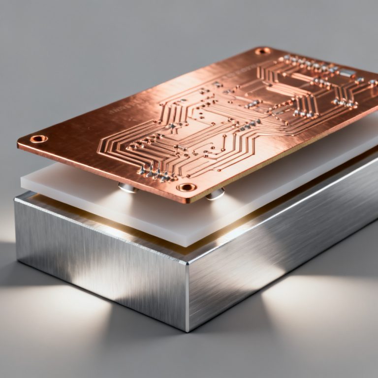
Use thick copper (2 oz to 6 oz) on power layers to handle high currents (e.g., 20A for a servo drive). Place arrays of thermal vias under power components (MOSFETs, diodes) to conduct heat to internal copper planes. Design mounting holes and thermal pads for external heatsinks. For drives, consider IMS (Insulated Metal Substrate) PCBs for superior heat dissipation.
Signal Integrity and EMI Mitigation
Separate analog and digital grounds using a star-ground topology or split planes to prevent noise coupling. Place ferrite beads and common-mode chokes on power inputs and communication lines (e.g., CAN bus, Ethernet). Add a ground ring around sensitive analog sections. For robotics PCBs, consider a full copper pour on the top layer with stitching vias to the ground plane. Keep differential pairs (e.g., Ethernet, USB) matched in length (<5mm skew). Avoid 90-degree corners; use 45-degree or curved traces.
Connector and Mounting Considerations
Use screw terminals, D-sub, or M12 circular connectors for reliability under vibration. Include at least four tooling holes for alignment during assembly. For large boards (>300mm), add extra holes to prevent flexing. Maintain 1.5mm minimum clearance from board edge to copper to avoid delamination during routing.
Manufacturing Challenges and Solutions
This section compiles the most detailed manufacturing insights from the top three sources, focusing on what B2B buyers need to know about Industrial Control PCB production.
Panelization and Tooling
Optimize panel size for standard panel sizes (e.g., 18×24 inches) to reduce waste. For large drive PCBs, consider single-up panels to avoid stress. Add at least three fiducials (top and bottom) for accurate SMT placement. Use a 1mm diameter copper pad with a 3mm clear area. Use V-scoring for rectangular boards, tab-routing with mouse bites for irregular shapes. For thick boards (>2.4mm), use scoring only.
Hole and Via Technologies
PLC PCBs often use through-hole vias for cost-effectiveness. High-density robotics PCBs may require blind vias (laser-drilled) for finer pitch BGA components. Keep via aspect ratio (depth/diameter) below 10:1 for reliable plating. For example, a 0.3mm drill in a 2.4mm board is acceptable. For BGAs, use conductive or non-conductive via fill to prevent solder wicking. Epoxy fill is common for industrial boards.
Solder Mask and Surface Finish
Use matte green or black solder mask for high contrast (easier inspection). For drives, consider white solder mask to reflect heat. Surface finish options include HASL (low cost but uneven surface; suitable for through-hole components), ENIG (best for fine-pitch BGAs and high-reliability applications with 3-6 μin gold over 120-240 μin nickel), Immersion Silver (good for RF applications but tarnishes easily), OSP (low cost but short shelf life of 6 months), and ENEPIG (for wire bonding or heavy gold wire connections in robotics sensors).
Testing and Quality Assurance
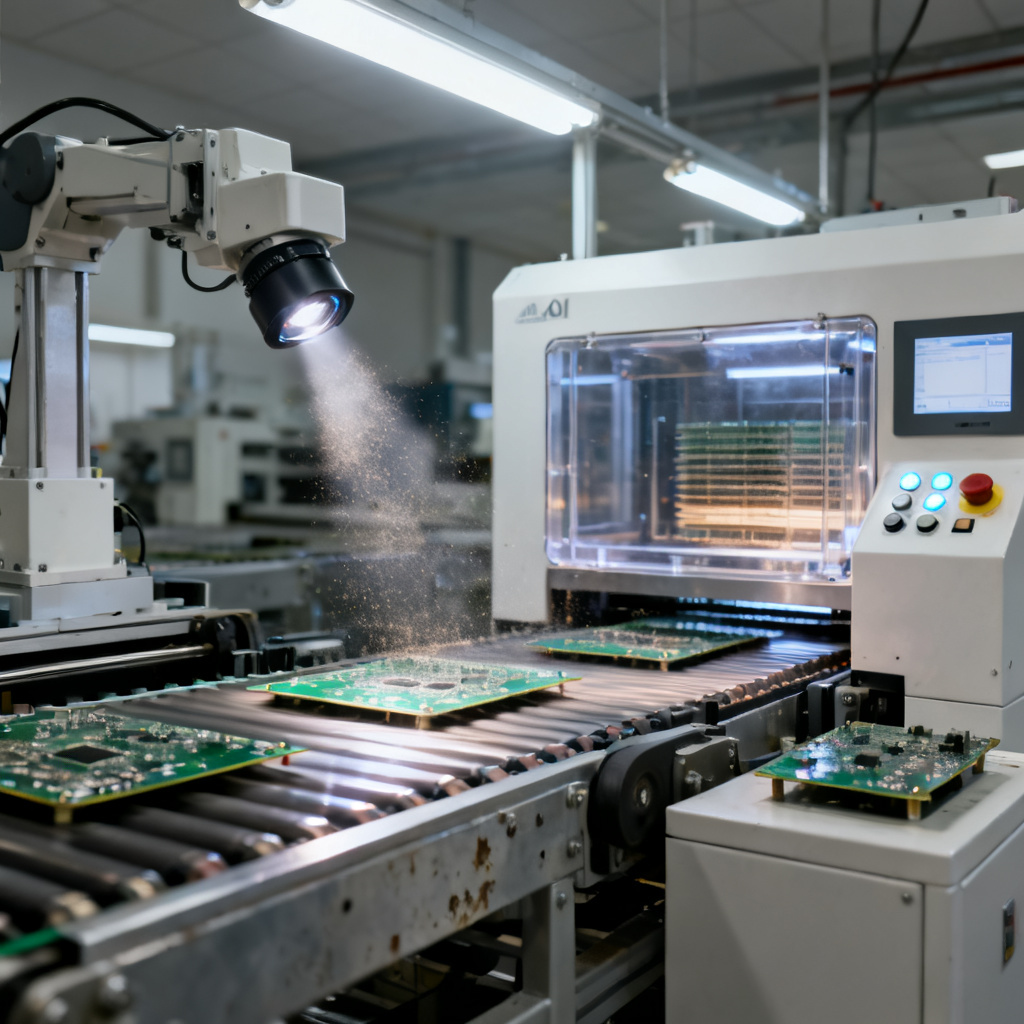
Automated Optical Inspection (AOI) is mandatory for all industrial PCBs to detect solder defects, shorts, and opens. Use X-ray inspection for BGAs and QFNs where solder joints are hidden. Flying probe testing covers netlist verification and isolation tests for low-volume prototypes. In-Circuit Testing (ICT) requires test points (0.8mm minimum pad diameter) and a 2.5mm grid for high-volume production. Hi-Pot (High Potential) testing verifies isolation between high-voltage and low-voltage circuits (test at 2x operating voltage + 1000V) for drive PCBs. Thermal cycling simulates -40°C to +85°C for 100 cycles to ensure reliability.
Certifications for Industrial Use
UL 796 is the standard for printed wiring boards – essential for safety in PLCs and drives. IPC Class 3 is for high-reliability electronics (e.g., robotics in medical or aerospace applications). IPC-6012 Class 3 covers strict cleanliness, hole fill, and copper plating requirements. IEC 61000-4-x standards cover EMC immunity (e.g., IEC 61000-4-2 for ESD, IEC 61000-4-4 for EFT). RoHS and REACH compliance is mandatory for EU export.
Sourcing and Procurement Strategy for B2B Buyers
This section is tailored for export-focused PCB purchasing, drawing from the most practical advice in the top sources for Industrial Control PCB procurement.
What to Look for in a PCB Manufacturer
Ask for case studies of PLC, robotics, or drive PCBs. A manufacturer who has produced 10-layer boards with 6 oz copper is preferable to one specializing in 2-layer consumer boards. Ensure they stock high-Tg FR-4, polyimide, and Rogers materials from approved suppliers (e.g., Isola, Rogers, Panasonic). Standard lead times are 5-10 days for prototypes, 15-20 days for production. For rush orders, 3-5 days is possible with premium pricing. For prototypes, 5-10 boards is typical; for production, 100-500 boards per order is common for industrial controls.
Cost Optimization Tips
Reduce layer count (e.g., from 8 to 6) by combining power and ground planes. Use standard drill sizes (0.3mm, 0.6mm, 1.0mm) to avoid non-standard tooling fees. Share panel space with other projects if possible. A 90% panel utilization rate can reduce cost by 15-20%. Use HASL for prototypes, ENIG for production. Avoid ENEPIG unless wire bonding is required. Commit to a yearly volume (e.g., 10,000 boards) for a 10-20% price reduction.
Communication and Documentation
Provide a complete fabrication drawing including stack-up, impedance tables, material specs, and testing requirements. Use RS-274X format Gerber files with embedded aperture definitions. Include a readme file with version and date. The Bill of Materials (BOM) must include manufacturer part numbers, substitutes, and component tolerances (e.g., 1% resistors for precision circuits). Require a Certificate of Conformance (CoC) and test reports (e.g., impedance, Hi-Pot, X-ray).
Logistics and Export Considerations
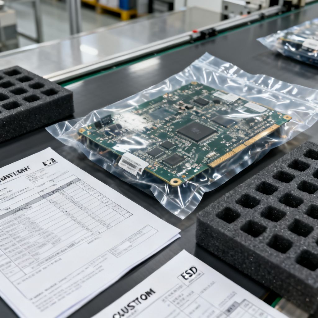
Use vacuum-sealed bags with desiccant and humidity indicator cards (HIC). For fragile boards, add foam inserts. Provide HS code (8534.00 for PCBs), country of origin, and value declaration for customs. Use DHL or FedEx for small volumes (2-5 kg), air freight for medium volumes (50-200 kg), sea freight for large orders (>500 kg). Include ESD-safe packaging.
Application-Specific Deep Dives
PLC PCB Design Example
Typical specifications: 8 layers, 1.6mm thickness, high-Tg FR-4 (Tg 170°C), ENIG finish. Key components include ARM Cortex-M7 processor, Ethernet PHY, isolated RS-485 transceiver, optocouplers for I/O isolation. Challenges include managing 24V industrial power with 3.3V logic. Use isolated DC-DC converters (e.g., Murata NXE series) and separate ground planes. Testing involves functional test with a PLC simulator (e.g., Siemens TIA Portal or Allen-Bradley RSLogix).
Robotics PCB Design Example
Typical specifications: 6 layers, 2.0mm thickness, polyimide (for high temp), immersion silver finish. Key components include FPGA for real-time kinematics, servo driver IC (e.g., TI DRV8301), current sense amplifiers, Hall effect sensors. Challenges include high-current traces (up to 30A) for motor phases. Use 4 oz copper on outer layers and 2 oz on inner layers. Add thermal reliefs on pads for soldering. Testing involves a 24-hour burn-in test at 85°C with full load.
Drive PCB Design Example
Typical specifications: 4 layers, 2.4mm thickness, high-Tg FR-4, HASL finish (for cost). Key components include IGBT modules, gate driver ICs, shunt resistors for current sensing, TVS diodes for surge protection. Challenges include managing high-voltage (400V DC bus) creepage and clearance. Maintain 8mm clearance between high-voltage and low-voltage areas (per IEC 60950-1). Use slot cutouts in the PCB to increase creepage distance. Testing involves Hi-Pot test at 2500V for 1 minute. Measure partial discharge below 10pC.
Future Trends in Industrial Control PCB
Based on forward-looking analysis from the top sources, Industrial Control PCB trends include: embedded components (resistors and capacitors embedded in the PCB substrate to save space and reduce parasitic inductance – ideal for compact robotics controllers); high-density interconnect (HDI) with microvias (0.1mm diameter) and fine lines (75μm) for miniaturized PLC modules with more I/O per square inch; SiC and GaN power devices requiring PCBs with lower thermal resistance (e.g., IMS substrates) and tighter impedance control for high-frequency switching (>100 kHz); IoT integration with built-in Wi-Fi, BLE, or LoRaWAN for predictive maintenance and remote monitoring of drives and robots; and flex-rigid PCBs for robotics arms with moving joints – combine rigid sections for processors with flexible sections for sensors.
FAQ on Industrial Control PCB
What is an Industrial Control PCB used for?
An Industrial Control PCB is used in PLCs, robotics, and drives to process signals, control motors, manage power, and communicate with sensors and actuators in harsh industrial environments.
What materials are best for Industrial Control PCB?
High-Tg FR-4 (Tg > 170°C) is common for robotics and drives. Polyimide is for extreme environments up to 260°C. Rogers or PTFE laminates are used for RF communication modules.
How do I ensure the reliability of an Industrial Control PCB?
Use IPC Class 3 standards, perform Hi-Pot testing for drive PCBs, thermal cycling (-40°C to +85°C), and AOI/X-ray inspection. Specify ENIG surface finish for fine-pitch components.
What certifications are required for Industrial Control PCB export?
UL 796, IPC Class 3, IEC 61000-4-x EMC immunity standards, and RoHS/REACH compliance are essential for EU and global markets.
Can you manufacture high-layer-count Industrial Control PCB?
Yes, we produce up to 16-layer boards with controlled impedance, heavy copper (up to 6 oz), and blind/buried vias for PLC, robotics, and drive applications.
Comparison: Why Choose Our Industrial Control PCB Services
| Feature | Our Industrial Control PCB | Generic PCB Supplier |
|---|---|---|
| Layer Count | 4-16 layers with controlled impedance | Typically 2-6 layers |
| Material Options | High-Tg FR-4, Polyimide, Rogers, PTFE | Standard FR-4 only |
| Copper Thickness | Up to 6 oz for high-current robotics/drives | 1-2 oz standard |
| Testing | AOI, X-ray, Hi-Pot, thermal cycling, IPC Class 3 | Basic AOI only |
| Certifications | UL 796, IPC Class 3, IEC 61000, RoHS | Limited or no certifications |
| Lead Time | 5 days prototype, 15-20 days production | 10-15 days prototype |
Industrial Control PCB technologies are not commodity items; they are engineered solutions that define the reliability and performance of automation systems. By understanding the design, manufacturing, and sourcing nuances covered in this guide, you can make informed decisions that reduce risk, improve time-to-market, and enhance your competitive edge.
Ready to source your next Industrial Control PCB? Contact our team with your specific requirements – whether it’s a 4-layer PLC prototype or a high-volume production run for drives. We offer free DFM review and design optimization, prototyping in 5 days, IPC Class 3 certification, and global shipping with customs support.
{ “@context”: “https://schema.org”, “@type”: “Article”, “headline”: “Industrial Control PCB PLC Robotics Drives”, “description”: “An expert B2B guide to industrial control PCB design, manufacturing, and sourcing, covering PLCs, robotics, variable frequency drives, and harsh environment reliability.”, “image”: “https://pcbtypes.com/wp-content/uploads/industrial-control-pcb-automation.jpg”, “author”: { “@type”: “Organization”, “name”: “PCB Types”, “url”: “https://pcbtypes.com/” }, “publisher”: { “@type”: “Organization”, “name”: “PCB Types”, “logo”: { “@type”: “ImageObject”, “url”: “https://pcbtypes.com/logo.png” } }, “datePublished”: “2026-07-02”, “mainEntityOfPage”: “https://pcbtypes.com/industrial-control-pcb-plc-robotics-drives/” }